Be warned. This dac employs completely off-standard thinking and uses METRIC measurements. Which can give most if not all people massive headaches. 
A measurable amount of chilli ingestion or the use of your own various forms of legal mind altering drugs is suggested. As is a pencil in your ear and ears full of wax and messed up hair so that you look like you know what you're talking about.
I certianly don't know what I'm doing, this just looks cool to me so I thought I'd share.
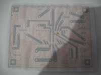
This PCB board design is meant to be traced onto a 70x90mm single sided or double sided copper PCB. Which keeps things cheap.
Every attempt has been made at isolation of each stage and providing the shortest path a priority to the power and shielding. A single point earth has been established and a choke should be placed in-between the B+ pad and the Vcc of the TDA1543 IC.
There is also an optional metal shield which surrounds the TDA1543 IC and solder tabs surround the IC to solder the shield to the bottom trace. This shield is also meant to cut straight across the two AOR and AOL traces which form an omega symbol. Please also note that you will need an external source for Vref.
You will need to download a copy of ExpressPCB to view and modify this design: (I like this software)
ExpressPCB - Free PCB layout and schematic software
Let me know if you find anything wrong with it or have things that you would like to suggest to improve the design.
The latest as of 25th July 2014:
It is not recommended that you build these until I have had a chance to build them myself (as of 25th of July 2014 I am only up to the pcb transfer stage, still waiting for components to arrive, specifically a drill press.), this thread is mainly for my own personal self discovery with this design and also to find any bugs or issues which I myself cannot see by my own. While you could theoretically print and build these traces you do so at your OWN RISK.
To get the latest file go to this post:
http://www.diyaudio.com/forums/digi...b-layout-suggestions-welcome.html#post4002866
A measurable amount of chilli ingestion or the use of your own various forms of legal mind altering drugs is suggested.
As is a pencil in your ear and ears full of wax and messed up hair so that you look like you know what you're talking about.I certianly don't know what I'm doing, this just looks cool to me so I thought I'd share.
This PCB board design is meant to be traced onto a 70x90mm single sided or double sided copper PCB. Which keeps things cheap.
Every attempt has been made at isolation of each stage and providing the shortest path a priority to the power and shielding. A single point earth has been established and a choke should be placed in-between the B+ pad and the Vcc of the TDA1543 IC.
There is also an optional metal shield which surrounds the TDA1543 IC and solder tabs surround the IC to solder the shield to the bottom trace. This shield is also meant to cut straight across the two AOR and AOL traces which form an omega symbol. Please also note that you will need an external source for Vref.
You will need to download a copy of ExpressPCB to view and modify this design: (I like this software)
ExpressPCB - Free PCB layout and schematic software
Let me know if you find anything wrong with it or have things that you would like to suggest to improve the design.
The latest as of 25th July 2014:
It is not recommended that you build these until I have had a chance to build them myself (as of 25th of July 2014 I am only up to the pcb transfer stage, still waiting for components to arrive, specifically a drill press.), this thread is mainly for my own personal self discovery with this design and also to find any bugs or issues which I myself cannot see by my own. While you could theoretically print and build these traces you do so at your OWN RISK.
To get the latest file go to this post:
http://www.diyaudio.com/forums/digi...b-layout-suggestions-welcome.html#post4002866
Attachments
Last edited:
Version 6.2:

This version has support for a 3v vref as a replacement for Vref output of the TD1543 IC.
You use the instructions as stated in this post by Flied Egg here:
http://www.diyaudio.com/forums/digi...ssian-tda1543-dac-off-ebay-4.html#post3965845
This version has support for a 3v vref as a replacement for Vref output of the TD1543 IC.
You use the instructions as stated in this post by Flied Egg here:
http://www.diyaudio.com/forums/digi...ssian-tda1543-dac-off-ebay-4.html#post3965845
Attachments

I'm not an expert by any means but you might consider the following points
1. The CS8412 ideally should have separate regulated power supplies as I am led to believe that the digital part is very noisy. Pin 24 is part of the digital section so you connect that to pin 7 and then supply pin 22 (the analog section) separately.
2.Can't see 680R resistors between pins 6/8 and +3vref - perhaps it is the software.
3. I like to tweak the final sound to taste - varying the PLL R/C components and coupling caps to suit the rest of the system so you might consider a temporary fixing until these are finalised.
Here is the 1st half of version 7.2 Alpha:

In this version you select which modes you want the CS8412 to do by bridging the M0-M3 traces and SEL traces to either earth or DB+ (5v). This version has thicker traces too which will aid in doing toner transfers to a PCB. (I know this from experience)
You will find the v7.2 expresspcb trace attached to this message.
It is not recommended that you build these until I have had a chance to build them myself (as of 25th of July 2014 I am only up to the pcb transfer stage, still waiting for components to arrive, specifically a drill press.), this thread is mainly for my own personal self discovery with this design and also to find any bugs or issues which I myself cannot see by my own. While you could theoretically print and build these traces you do so at your OWN RISK.
Attachments
Last edited:
I hereby christen this revision "Purple Monkey Dishwasher".
The idea is that the spacious PCB allows you to hang large coupling capacitors off the edge when using 2 pin terminal screw thingies.Also all of the good stuff like really super close capacitors (I'll be using a 10uF one on my TDA1543 and a ceramic 0.1uF)
And star grounding...
And Wire holes as indicated on the PCB as "W" for input from an external battery 3v Vref source.
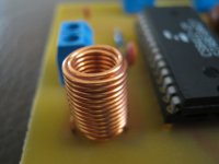
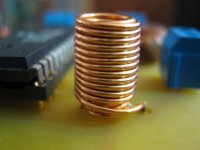
And a spot for a transformer (make it yourself using a small toroid core.) for coupling your CD player's S/PDIF to the input to the CS8412.
And a small coupling capacitor to keep the nasty stuff out.
I'm off to bed, enjoy!
Version 7.2.1 of the CS8412 part A.
&
Version 8.1.1 of the TDA1543 part B.
Part A

Part B

Both are bundled in the same zip file as attached to this message:
The idea is that the spacious PCB allows you to hang large coupling capacitors off the edge when using 2 pin terminal screw thingies.Also all of the good stuff like really super close capacitors (I'll be using a 10uF one on my TDA1543 and a ceramic 0.1uF)
And star grounding...
And Wire holes as indicated on the PCB as "W" for input from an external battery 3v Vref source.
And a spot for a transformer (make it yourself using a small toroid core.) for coupling your CD player's S/PDIF to the input to the CS8412.
And a small coupling capacitor to keep the nasty stuff out.
I'm off to bed, enjoy!
Version 7.2.1 of the CS8412 part A.
&
Version 8.1.1 of the TDA1543 part B.
Part A
Part B
Both are bundled in the same zip file as attached to this message:
Attachments
Last edited:
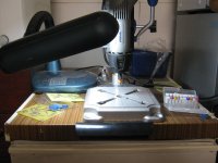
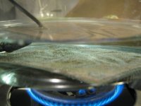
Progress has been made with regards to pcb printing/drilling.
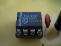
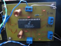
If anyone is interested, this is what a genuine TDA1543A looks like. (Pulled from a Sony CDP)
I am aware of the incompatability of the CS8412 with the TDA1543A, Will be finding another IC capable of Japanese digital output.
I'm at the moment designing the LM317 super capacitor power supply. Its a bit difficult because I need to make it capable of automatically switching from a solar 12v DC power source to 240v AC and back again during a blackout.
Attachments
-
 Picture 024s.jpg262.9 KB · Views: 71
 -
 Picture 023s.jpg268.6 KB · Views: 85
 -
 Picture 022s.jpg380.9 KB · Views: 102
 -
 Picture 020s.jpg230.9 KB · Views: 91
 -
 Picture 019s.jpg340.9 KB · Views: 97
 -
 Picture 016s.jpg360.1 KB · Views: 88
 -
 Picture 009s.jpg266.3 KB · Views: 89
 -
 Picture 007s.jpg208.4 KB · Views: 82
Last edited:
I went and gave my phone number to someone who will almost certainly guarantee to give me a job.
I feel excited about it.
I have some money saved up and no outgoing expenses at all so I should be able to have about 8 weeks to look for work if I only pay for food.
I'm sick of being dependent on welfare, its time to try and go for jobs again.
I feel excited about it.
I have some money saved up and no outgoing expenses at all so I should be able to have about 8 weeks to look for work if I only pay for food.
I'm sick of being dependent on welfare, its time to try and go for jobs again.
Last edited:
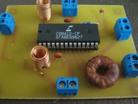
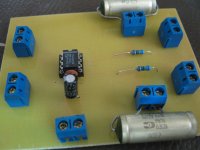
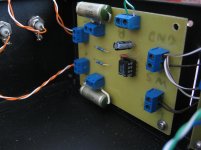
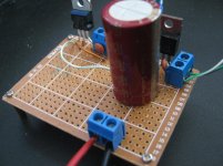
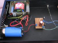
Got pictures of the prototype.
It sounds great. Very soft but accurate and sharp. It does lack bass but it makes up for it with tons of clarity.
The only thing that I have to compare it to is a TDA1541 (NON-A) board pull from a Marantz CD-65 CD Player, unmodded with the op-amps still in place. And the TDA1543 Russian dac kit "Hypnosis" with its cheap chinese knockoff/fake TDA1543 IC.
~ Compared to an unmolested Marantz CD-65:
It sounds at least 90% as good as the TDA1541 which is about what I expected. It does have a taste of the 3D clarity which the TDA1541 brings to the table but it is not completely immersive as the TDA1541 can be.
~ Compared to the eBay TDA1543 Russian DAC Kit "Hypnosis"
In comparison to this one the Russian DAC has a sharp and nasty high end. This Anarchist DAC has seemed to mellowed everything out a bit. It does have the same 3D clarity as the Russian DAC but it just sounds smoother and less fatiuging.
~ Compared to your average run-of-the-mill CD player with a 1-Bit dac, this is far far superior.
All of these observations are with 4 hours of burn-in.
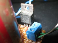
Also pictures of what a 100% Genuine AN7805 looks like. (Pulled from a parts bin that dates back to the 1970s.)
The Genuine AN7805 is dedicated for Analog Power supplies only and solely feeds the TDA1543.
It sounds great. Very soft but accurate and sharp. It does lack bass but it makes up for it with tons of clarity.
The only thing that I have to compare it to is a TDA1541 (NON-A) board pull from a Marantz CD-65 CD Player, unmodded with the op-amps still in place. And the TDA1543 Russian dac kit "Hypnosis" with its cheap chinese knockoff/fake TDA1543 IC.
~ Compared to an unmolested Marantz CD-65:
It sounds at least 90% as good as the TDA1541 which is about what I expected. It does have a taste of the 3D clarity which the TDA1541 brings to the table but it is not completely immersive as the TDA1541 can be.
~ Compared to the eBay TDA1543 Russian DAC Kit "Hypnosis"
In comparison to this one the Russian DAC has a sharp and nasty high end. This Anarchist DAC has seemed to mellowed everything out a bit. It does have the same 3D clarity as the Russian DAC but it just sounds smoother and less fatiuging.
~ Compared to your average run-of-the-mill CD player with a 1-Bit dac, this is far far superior.
All of these observations are with 4 hours of burn-in.
Also pictures of what a 100% Genuine AN7805 looks like. (Pulled from a parts bin that dates back to the 1970s.)
The Genuine AN7805 is dedicated for Analog Power supplies only and solely feeds the TDA1543.
Attachments
Last edited:
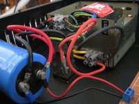
I did have extensive problems with digital noise appearing on the analog side however properly earthing each stage to each other solved these problems. Also earthing the CS8412 to the chassis solved the final problem.
It was interesting listening to the storm of digital noise which we know is there but we cannot hear. It went silent during transitions and came on like a storm during loud passages.
I resolved the earthing problems in 3 stages.
First I did some research and read a post regarding properly terminating I2S lines with a 0.01uF ceramic capacitor across the SDATA and Ground. This ended up not fixing the problem.
Then I realized that I really should have dedicated earth lines for each I2S wire, BCK/WS/SDATA, So I ran 3 pairs of wire from the pins of the CS8412 and terminated all 3 earth lines at the earth on the screw terminal of the DATA/GND on the TDA1543 Board. This improved things gradually.
Then I realized that an earth wire coming from the CS8412 power-earth terminals to the chassis improved things considerably.
The problem primarily is that I don't have my BNC analog outputs and digital SPDIF BNC connector floating from the chassis (The washers that I need to do this with are playing hide and seek), So I'm assuming (correctly hopefully) that all of the digital noise was going through my analog stages and through to the chassis.
Last edited:
This is what I've done many years ago...I believe I still have schematic and PCB layout Orcad files...Drop me a PM if you need it....
An externally hosted image should be here but it was not working when we last tested it.
An externally hosted image should be here but it was not working when we last tested it.
An externally hosted image should be here but it was not working when we last tested it.
Last edited:
- Status
- This old topic is closed. If you want to reopen this topic, contact a moderator using the "Report Post" button.
- Home
- Source & Line
- Digital Line Level
- TDA1543 Anarchist DAC PCB layout. Suggestions welcome.