It is irrespective of implementation, chip or other, it is what it is.
I have a good idea, lets design from committee with one designer, sorry.. dictator.
Oops, you already have")
How anyone can get half of it right, and the other half so completely wrong should be classed as the 8th wonder of the world, or are we up to number 9 yet?.
Sun
I have a good idea, lets design from committee with one designer, sorry.. dictator.
Oops, you already have
How anyone can get half of it right, and the other half so completely wrong should be classed as the 8th wonder of the world, or are we up to number 9 yet?.
Sun
Follow, I don't think that you do.
If you look at the PCB is shows a connection point for the supply lines. If you look at the schematic it shows what would be included on the PCB and my point stands.
And none of this addresses the galvanic issue, be it true, false or imaginary.
Heres to imagination !!
Sun
If you look at the PCB is shows a connection point for the supply lines. If you look at the schematic it shows what would be included on the PCB and my point stands.
And none of this addresses the galvanic issue, be it true, false or imaginary.
Heres to imagination !!
Sun
Last edited:
Very interested in this topic. I use 1545 chip and look for something different.
Not sure why so aggressive though
Galvanic?.. like insulating dissimilar metals?
Looks to me that Luke is correct.
Hi,
I think you need to look at firstly the PCB outline… (without the regulators on board - there is no PCB with regulators on board to this thread !!)
And then look at the simulated schematic, with the highlighted area in red to be included with the PCB.
Easy to make a dull point, harder to make a poignant one. I'll take your comment re: 'aggressive' in stride.
Sun
Hi Sun Tzu,
I believe in this context it would be more appropriate for you to high light & advice
instead. After all we all are diyers & would be great that those with more experience
would lend their views to help us all learn & improve our knowledge. Me my know
how is mostly in tube.
Cheers
I believe in this context it would be more appropriate for you to high light & advice
instead. After all we all are diyers & would be great that those with more experience
would lend their views to help us all learn & improve our knowledge. Me my know
how is mostly in tube.
Cheers
Besides the mistake might not be a mistake as Ryan surely would again rearrange the layout to make the necessary changes on the pcb & if a mistake is spotted would be rectified on the
final pcb & if not then there's where guys like you with more knowledge would hopefully
chime in to assist right ?
final pcb & if not then there's where guys like you with more knowledge would hopefully
chime in to assist right ?
PSU schematics correction.
Thanks for all the comments and input, it's all appreciated and ill take it all in my stride.
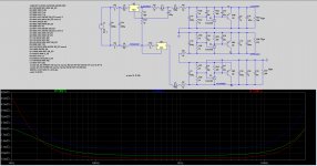
Just a small correction in the schematics I posted earlier. The load for -15V represented as R27 in the below schematics should of course be referenced to GND, as should all the caps for this supply.
Image attached - Updated schematics and output impedance graph.
Seems -15V is the best performer in this configuration. All supplies simulate under 3mΩ in the audible frequency range.
I must mention that I have every intention to test everything before it is stamped for approval. I'll base this decision on a comparison against V1 using my current Salas shunt regs, Iancanada FIFO 1 with I2S to PCM converter.
Thanks for all the comments and input, it's all appreciated and ill take it all in my stride.
Just a small correction in the schematics I posted earlier. The load for -15V represented as R27 in the below schematics should of course be referenced to GND, as should all the caps for this supply.
Image attached - Updated schematics and output impedance graph.
Seems -15V is the best performer in this configuration. All supplies simulate under 3mΩ in the audible frequency range.
I must mention that I have every intention to test everything before it is stamped for approval. I'll base this decision on a comparison against V1 using my current Salas shunt regs, Iancanada FIFO 1 with I2S to PCM converter.
Attachments
Greg Stewart x2
ppap64 x 2 V2
Peterma x 3 V2
kenlaumm x 2 V2
j.burtt x 2 v2
crowlie x3 V2
ed linssen x2 V2
mravinsky x2 V2
palmito x2 V2
xaled x2 V2
noizas x4 V2
wlowes 1x V2
pchw 2x V2
badrisuper X 1
tagheuer x2 V2
Jaffrie x2 V2
Luke X2 V2
lll X2 V2
unixdeveloper x2 V2
BDL x1 V2
zany x2 V2
flyboi x2 V2
GaryB x2 v2
1Hz - 10M Simulation Plot.
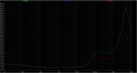
Attached is a plot of the z-out for all three supplies from 1hz - 10meg from the most recent schematics update. The simulation includes 100nF MLCC C0G/NP0 and a 1uF Panasonic stacked film. Adjusting these caps has a rather big impact on the performance past 100k. Note that C0G/NP0 are comparable to polystyrene for distortion, temperature stability etc., ESR is single number milliohm.
Ive also attached a Technote on MLCCs - 'Is 0.1μF sufficient for bypass capacitor?" - A fairly interesting read.
Attachments
Attached is a plot of the z-out for all three supplies from 1hz - 10meg from the most recent schematics update. The simulation includes 100nF MLCC C0G/NP0 and a 1uF Panasonic stacked film. Adjusting these caps has a rather big impact on the performance past 100k. Note that C0G/NP0 are comparable to polystyrene for distortion, temperature stability etc., ESR is single number milliohm.
Ive also attached a Technote on MLCCs - 'Is 0.1μF sufficient for bypass capacitor?" - A fairly interesting read.
Ryan,
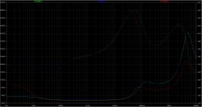
check the phase slope around 5 MHz, it could ring.
Above post should read:
Andrea,
Attached is the impedance plot for all 3 supplies vs phase, appreciate your time.
Cheers.
Thanks for all the comments and input, it's all appreciated and ill take it all in my stride.
Hi,
If so then you would answer the questions about 'galvanic isolation' which I do not understand, and also about 'charging pulse of 15 -10x 3A' into 5,000uF, also which I do not understand..
Maybe it is you also who does not understand with these things. But you appreciate it, so please explain.
My concern is that if you understand these things and avoid to answer, then for what reason (commercial?) and if to answer unknown then questions the valid of your PCB, as was already suggested by Sun Tzu
RGS,
Doce.
Besides the mistake might not be a mistake as Ryan surely would again rearrange the layout to make the necessary changes on the pcb & if a mistake is spotted would be rectified on the
final pcb & if not then there's where guys like you with more knowledge would hopefully
chime in to assist right ?
Hi,
Any mistakes would be that of the designer.
You need to understand that.
He is not open to suggestion = correction. "I take it all in my stride" and never answer simple question like 'what about galvanic isolation', 'why for the cap between supply lines -15 to -5 and +5v'.
ala Eldam comment to him "all is under control"
You need to understand that this is not a group project.
That is my point.
Check the forum, check the track record.
You give, he take… and then sell it back.
Still, missing the major points of the original "any good 1541A kit" thread.
Amazing (not really)_
So, in the end.. go milk a duck.
Sun
Thanks for all the comments and input, it's all appreciated and ill take it all in my stride.
Just a small correction in the schematics I posted earlier. The load for -15V represented as R27 in the below schematics should of course be referenced to GND, as should all the caps for this supply.
Image attached - Updated schematics and output impedance graph.
Seems -15V is the best performer in this configuration. All supplies simulate under 3mΩ in the audible frequency range.
I must mention that I have every intention to test everything before it is stamped for approval. I'll base this decision on a comparison against V1 using my current Salas shunt regs, Iancanada FIFO 1 with I2S to PCM converter.
Ryan, R5 and R7 are 1p??? 1 Ohm I guess?
Mmh.
I reading back now the history…
Not sure that you are correct.. but very much to read.
Doce
Theres a line pending to 'milk the duck', so you need take a number and wait!
(oh, and thank you for your custom - here is a supplementary spittoon)
Sun
- Status
- This old topic is closed. If you want to reopen this topic, contact a moderator using the "Report Post" button.
- Home
- Source & Line
- Digital Line Level
- Group buy/Interest list - TDA1541A Core board.