Hi T & mmerrill99:
It makes sense ... And the virtual ground also sounds attractive but I reckon it would mean more electronics and PSUs, right? The attractiveness of the pure DSD FF solution was that it could be done with a simple FF which with a good PSU e.g. could directly drive a headphone or amplifier. But given the quite high distortion level (I think it was about - 80 dBs) at 1 mA I let it go ...
Thanks for the link ;-) And, yes, I guess this would make for a sensible solution. Many things to consider ...
...
I think we might have misunderstood eachother here ...? What I meant to say was that the jitter typically goes down when the voltage to a logic IC is increased. As I read your comment that is also what you say - related to propagation delay ... ?
Well, IMHO their sonic imprint can be quite significant. However, generally speaking, I do agree that many other factors are important as well. Not least grounding and proper PSU design.
With respect to a balanced DSC version I reckon one of the challenges could be to time-wise distribute a low jitter clock to all of the FF ICs. FFs in high Nos have significant input capacitances and with the clock rise times present the clock driving circuit would need to be able to supply high currents at low jitter values. One partial work-around for this could be the 74AUP series logic which typically have 0.8 pF input capacitances ... They are, however, Schmitt triggered - something that I don't know if matters in terms of jitter/performance. And low voltages ...
Cheers,
Jesper
Hi Jesper,
Read my reply above WRT running into virtual ground. There is mechanism of non linearity with OP voltage swing. When FF goes high, if there is swinging voltage on OP of resistor network (or even 1 resistor) the 'on' resistance of FF will change according to current. This will result in distortion. If the resistor is driven into virtual ground, each 'on' and 'off' (high and low) will see exactly same current.
It makes sense ... And the virtual ground also sounds attractive but I reckon it would mean more electronics and PSUs, right? The attractiveness of the pure DSD FF solution was that it could be done with a simple FF which with a good PSU e.g. could directly drive a headphone or amplifier. But given the quite high distortion level (I think it was about - 80 dBs) at 1 mA I let it go ...
Straight inverters can have very low phase noise.
http://www.ham-radio.com/sbms/LPRO-101.pdf
check page 18 for comparison of various squaring circuits. 74AC04 does not degrade Wenzel ref OCXO at 10Hz offset. LVC or Potato should be better again. I'm not sure how much more jitter FF adds. It's also determined by power supply as CMOS have poor PS rejection.
Probably to do this really well you need separate VLN reg for each FF or at a minimum, very good decoupling for each FF.
Thanks for the link ;-) And, yes, I guess this would make for a sensible solution. Many things to consider
... I'm not sure about that. Prop delay goes down as supply voltage goes up. Worth checking data sheets.
I think we might have misunderstood eachother here ...? What I meant to say was that the jitter typically goes down when the voltage to a logic IC is increased. As I read your comment that is also what you say - related to propagation delay ... ?
I think the resistors probably matter the least compared to other issues. As long as they have decent tempco.
Well, IMHO their sonic imprint can be quite significant. However, generally speaking, I do agree that many other factors are important as well. Not least grounding and proper PSU design.
With respect to a balanced DSC version I reckon one of the challenges could be to time-wise distribute a low jitter clock to all of the FF ICs. FFs in high Nos have significant input capacitances and with the clock rise times present the clock driving circuit would need to be able to supply high currents at low jitter values. One partial work-around for this could be the 74AUP series logic which typically have 0.8 pF input capacitances ... They are, however, Schmitt triggered - something that I don't know if matters in terms of jitter/performance. And low voltages ...
Cheers,
Jesper
Didn't the balanced version have a much lower THD?Hi T & mmerrill99:
It makes sense ... And the virtual ground also sounds attractive but I reckon it would mean more electronics and PSUs, right? The attractiveness of the pure DSD FF solution was that it could be done with a simple FF which with a good PSU e.g. could directly drive a headphone or amplifier. But given the quite high distortion level (I think it was about - 80 dBs) at 1 mA I let it go ...
What sensibly priced resistors (there are 64 & possibly 128 of them) are you thinking would best suit this role?Well, IMHO their sonic imprint can be quite significant. However, generally speaking, I do agree that many other factors are important as well. Not least grounding and proper PSU design.
In the R2R approach used in the Soekris DAC, the clocks are fed from FPGA through capacitor into 595 logic & measured distortion is very low. Not sure what logic chip is used?With respect to a balanced DSC version I reckon one of the challenges could be to time-wise distribute a low jitter clock to all of the FF ICs. FFs in high Nos have significant input capacitances and with the clock rise times present the clock driving circuit would need to be able to supply high currents at low jitter values. One partial work-around for this could be the 74AUP series logic which typically have 0.8 pF input capacitances ... They are, however, Schmitt triggered - something that I don't know if matters in terms of jitter/performance. And low voltages ...
Cheers,
Jesper
Hi mmerrill,
Best regards,
Jesper
To be honest I don't remember whether I measured the distortion balanced or SE. My main objective was to observe when the logic started distorting and I remember it being pretty clearly happening around 1 mA.Didn't the balanced version have a much lower THD?
... Well, soekris to my knowledge uses Susumu RG resistors, however, their sound imprint is not really my preference. Apart from the TX2575s the most balanced resistors I can think of are the RN65E from Vishay/Dale. Incidentally, these resistors also have a very low distortion level according to simon7000. S102 could be second choice (can be bought second hand on ebay) and there's takman, rhopoint etc. ... but to my ears the most transparent ones by a good margin is the TX2575, Charcroft CAR. So not really a clear second option here from my perspective..What sensibly priced resistors (there are 64 & possibly 128 of them) are you thinking would best suit this role?
I don't know either. But the challenge is that with the HF content of a square clock signal the small capacitances on the inputs of the logic and the characteristic PCB trace impedances will load the sending IC significantly. I have simulated this and even with low Nos of IC inputs (8 pcs, 4 pF load each) the currents can reach ~65 mAs - which I think will be a challenge for a precision clock. Using multiple clock sending gates IMHO is not an optimum solution as their timing is not entirely the same ... so I think it would be a challenge to feed maybe 32 or 64 FF gates with a good clock ...In the R2R approach used in the Soekris DAC, the clocks are fed from FPGA through capacitor into 595 logic & measured distortion is very low. Not sure what logic chip is used?
Best regards,
Jesper
I don't know either. But the challenge is that with the HF content of a square clock signal the small capacitances on the inputs of the logic and the characteristic PCB trace impedances will load the sending IC significantly. I have simulated this and even with low Nos of IC inputs (8 pcs, 4 pF load each) the currents can reach ~65 mAs - which I think will be a challenge for a precision clock. Using multiple clock sending gates IMHO is not an optimum solution as their timing is not entirely the same ... so I think it would be a challenge to feed maybe 32 or 64 FF gates with a good clock ...
Best regards,
Jesper
AFAIK, many FIRDACs(Signalyst topology) use discrete FFs like HC595. The input capacitance of them becomes large if you use 32 or 64 taps, which means a tough challenge to drive them successfully.
One solution for this is to use FPGA which has an internal clock driver capable of more than 100 FFs without degradation. The output buffer of FPGA has a various driving capability (from 2mA to 16mA) with less ringing than a normal discrete logic.
Furthermore, FPGA can adjust the different propagation delay between L to H and H to L. Spartan6 can compensate them by almost 50ps step. I don't have time now to design FIRDAC by FPGA. But it's not difficult to make PCB because 64 taps can be done by QFT package which is possible to solder manually. I'm looking forward to measuring FIRDAC by FPGA instead of discrete logic.
A P.S.:
If you can describe what sound qualities you are after in a resistor I might be able to suggest which resistor(s) go in that direction ...
Best regards,
Jesper
What sensibly priced resistors (there are 64 & possibly 128 of them) are you thinking would best suit this role?
If you can describe what sound qualities you are after in a resistor I might be able to suggest which resistor(s) go in that direction ...
Best regards,
Jesper
A P.S.:
If you can describe what sound qualities you are after in a resistor I might be able to suggest which resistor(s) go in that direction ...
Best regards,
Jesper
I wouldn't get too caught up on shelling out for expensive resistors.
As stated many many times, unity weighted DAC's like this are not like R2R DAC's where resistor accuracy directly impacts distortion.
The accuracy of the resistor will have virtually no effect on distortion. As such it's a safe presumption that the resistor quality will be less critical.
I would just go far a HQ, good sounding, reasonable priced MF resistor.
T
Yes my thoughts are similar to yours, Zen - I think you mentioned before that impulse response & tempco were the two main characteristics needed for resistors in this role so I wondered if there were any resistors that fulfill these criteria? I've seen resistors that have been measured for pulse response but this is usually in the field of power resistors & their change in resistance with sustained power pulses. I have seen resistors specified for use at RF but these tend to be expensive.
Signalyst used resistor networks "Since most of the networks are designed to be used as bus termination networks, they have somewhat favorable switching characteristics". This would seem to be an eminently sensible approach for resistor selection - only downside I can see is possible tempco issues in resistor arrays - pulse handling of multiple resistors on same substrate. Anybody experimented with this or have further thoughts?
What role are the resistors performing - providing a stable impedance that the FF outputs see - converting V pulses to current pulses? In other words why is the direct output from the FF pins used?
From what I understand of a moving average filter, the averaging sorts out a number of potential issues - there is less sensitivity to the accuracy of the resistors - is there not also therefore less sensitivity to the variation in FF output pin impedance differences between a 1 pulse & 0 pulse processing?
There is less sensitivity to jitter but higher sensitivity to PS quality as there's 0 PSRR in FFs
WRT resistors - I would just use 1 watt MF. PRP or Takman are great resistors. 1 watt will be less sensitive to thermal modulation - if that is even a concern.
WRT FF OP impedance variation. Also as stated, this is a result of running resistor network in voltage mode (allowing voltage swing) as opposed to current, (driving a virtual ground). If you use 'current mode' then each 'on' of a particular FF will always be the same impedance (given ideal PS etc). Variation of 'on' resistances between different FF's is as per resistors, not critical.
The rest is PS noise (Cmos logic has poor PS rejection), clock jitter etc. I think these issues are much more important than resistor types.
And then there is the RTZ coding issue I mentioned earlier which nobody appears to want to comment on. I'd be interested to see distortion comparison between RTZ and non RTZ implementation.
Z
There is less sensitivity to jitter but higher sensitivity to PS quality as there's 0 PSRR in FFs
Very much so.
I've tried Reflektor D PS from the forum that out performs all the other ones I've tested.
I have a question for you Miska - would it not be better to use differential OP flip flops for a balanced design?
I'm wondering if the bulk of non linearities are due to inherent non RTZ nature of DSD stream. As such I would think the fastest dif OP logic would give best results. Something like 16 x Potato 74G74 dual FF should work well.
Otherwise is it possible to integrate RTZ coding?
Now the DSD stream can be considered as fancy PWM generated by the modulator. For RTZ-like operation, one option I was considering to try out for DSC2 are fast analog mux chips. They have "break before make" behavior built-in. I'm a bit curious how it would perform in practice.
Using such differential FF is probably good option too.
At DSD512 speed, RTZ coding would be feasible with CPLD and provision for it could be easily added to HQPlayer (to take into account the 2x rate difference). So CPLD could "reset" every second sample.
Maybe I should put a small CPLD on DSC2? That would allow some experimentation...

Would a logic AND gate do the RTZ job?
DSD stream on A input & DSD clock on B input
Output 1,0 for 1 input & 0,0 for 0 input
Then use double clock speed for DSD clock in 595 clocking.
Anybody tried this or am I missing something?
I don't think so, because you'd need a third symbol that is not naturally occurring in the data stream. Now '0' is full scale negative voltage and '1' is full scale positive voltage...
I don't think so, because you'd need a third symbol that is not naturally occurring in the data stream. Now '0' is full scale negative voltage and '1' is full scale positive voltage...
Sorry, I don't follow - can you expand on this, please?
Do you mean that in the DSD stream 0 is fully negative & 1 fully positive but with RTZ we just want a return to halfway between full neg & full pos i.e to zero?
Last edited:
But is it not that a series of '0's is full scale negative, not just singular '0's interspersed between existing '1's & '0's?
I can see how it might bias the output more negatively i.e result in an different output offset - is this the issue you are alluding to?
Is this why the CS4303 DAC datasheet states
"Return-to-zero coding is used where each occurrence of a '1' is 75% high & returns low for 25% of the bit period"?
I can see how it might bias the output more negatively i.e result in an different output offset - is this the issue you are alluding to?
Is this why the CS4303 DAC datasheet states
"Return-to-zero coding is used where each occurrence of a '1' is 75% high & returns low for 25% of the bit period"?
Last edited:
But is it not that a series of '0's is full scale negative, not just singular '0's interspersed between existing '1's & '0's?
I can see how it might bias the output more negatively i.e result in an different output offset - is this the issue you are alluding to?
Is this why the CS4303 DAC datasheet states
"Return-to-zero coding is used where each occurrence of a '1' is 75% high & returns low for 25% of the bit period"?
Just a quickie, WRT 25% - exactly. Which implies a much faster clock rate if everything is to be reclocked, AFAICS. This in itself carries some liabilities.
I'm wondering if you can do it with same clock and a delay line. Have to think about this.
More later, have to go.
T
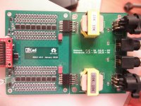
I assembled the DSC layout on the differential FF 74VHC175.Using such differential FF is probably good option too.
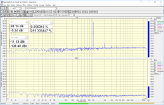
Works badly. I again hear noise (murmur) as in the original non-differential DSC1 scheme. The overall noise level also deteriorated compared to v2.5 and v2.6.
Attachments
Last edited:
Do you mean that in the DSD stream 0 is fully negative & 1 fully positive but with RTZ we just want a return to halfway between full neg & full pos i.e to zero?
Yes, zero would be between the two extremes. Which is now produced by the offset that happens when value distribution is 50/50[1]. In my design there's the decoupling capacitor to get rid of the offset. In this way, sure, DC latch-ups to either rail don't work. Which can be also good...
So you don't get full rail voltage on the output in case there's a software problem and the DAC gets all 0's (or 1's which is more unlikely to happen though)...But one could instead also apply static offset to have negative current. In fact I should have tried I/V setup that is sinking to virtual +2.5V reference...
With pulse trains the current setup works well though, but closer to DC it can get tricky.
[1] If you put HQPlayer to play silence file you get fancy version of such. If you just pause the playback, you get less fancy static pattern.
I assembled the DSC layout on the differential FF 74VHC175.
Works badly. I again hear noise (murmur) as in the original non-differential DSC1 scheme. The overall noise level also deteriorated compared to v2.5 and v2.6.
That seems odd? Any thoughts on what could be going on?
- Home
- Source & Line
- Digital Line Level
- Signalyst DSC1