8. The important file is amanero_mute_pins
It takes a bit mask, so for D5 on Cronus, do this:
....
One can test this experimentally - when not playing, you should have HIGH on the said pin and when playing - LOW.
....
Let me know.
Hiyas!
I feel a bit scrambled with mute_pins and amanero_mute_pins - what's the difference?
The task I'm trying to complete is slightly aside of this topic - it's 8-channel AKM dac, so, except of getting the mute pin out of data pin array (I emailed you already about this) I need actually 2 outputs - reset (when Fs changes) and actual mute.
What are the roles of 2 mute outputs?
Thank you.
Way back at post 563 there was a discussion about logic distortion starting at around 1mA.
I assume this 1mA relates to the nominal current through each resistor.
I see the current recommended resistors are 4k7-6k4 range, hence I assume set to be just under or on this point.
Has further analysis been done to qualify this, does anybody have any measurements they have saved?
Is the cause of the distortion yet understood?
Many thanks
bs
My immediate thought jumped to the suggestion that distortion arises from driving into ground, not a virtual ground, however I assume this would be fairly linear and not begin to occur at a point.
I also wonder is this still a consideration with the later differential design?
...
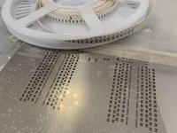
Vishay TNPW12064K99BEEN (4.99K, 0.1%, 25ppm) x900, at what appears a good bargain online at 3.7c each.
...
Seems some generic high-reliability resistor...
i guess here you have to spend some more money to gather better performance... you need to aim for high impulse current handling and lower noise.
Vishays PAT are a good choice, as for some type of MELF.
anyway, any tantalum-nitride thin film resistor will be up to the task.
Hi gionag, many thanks for your feedback on resistor choice.
Yes exactly. This is not my first choice of resistor, only something I felt practical to begin experimentation with at low cost as I plan to try a few iterations of changes. I intend to initially focus efforts elsewhere, not on resistor make/series choice first.
Saying that, I thought these looked ok!
- Thin film
- Same 25ppm TCR as the best available in Vishay PAT or Vishay MELF 0204.
- Same 0.05uV/V Current noise as the Vishay MELF 0204 (not sure of PAT current noise)
- 0.1% (although this doesnt matter)
- Not sure of Voltage coefficient though.
With PAT 4.99K about US$0.59each/100-$0.51/500 from Mouser, and low TCR MELFS even more, at about 1/16th the cost I thought these were ok budget choice!
If you see a specific problem with them then please let me know!
you can try whatever you feel... is the whole point of DIY.
i was just suggesting what is considered a "proved" solution to get good/best result from the get go.
at any rate... report back what you find out !
")
My immediate thought jumped to the suggestion that distortion arises from driving into ground, not a virtual ground, however I assume this would be fairly linear and not begin to occur at a point.
I also wonder is this still a consideration with the later differential design?
I asked couple of times what value for end resistors suite best, for 3.3V and for 5V logic. But without answer.
Thanks for point the post where this issue discussed
cheers
.
Hello, I have a problem with DSC2 5.2. : The right channel is heard with much less volume than the left one. I have noticed that U21 is very hot, I do not know if it has anything to do, I have also been able to measure that in right channel there is continuity between gnd and +.
Any idea of the problem?
Thanks
Any idea of the problem?
Thanks
Any advantage to using 74595 instead of using 74164?
Because I see the LATCH pin on 74595 is tied together with a CLOCK pin.
At least I think both of 74595 and 74164 can be used for this particular design.
Regards,
TJ.
the 595d seems to have just an hair of more bandwidth...
I got good results with the 74LVC8T595.
With these registers, you can separately supply high-quality power only to the output stage.
to my knowledge you have never released a board version based upon the 8T595... right ?
to my knowledge you have never released a board version based upon the 8T595... right ?
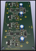
There is a real prototype with bisesik transformers.
It sounds good.
But the release is delayed due to many problems with COVID.
There will be a choice of transformers or an active output.
Attachments
There is a real prototype with bisesik transformers.
It sounds good.
But the release is delayed due to many problems with COVID.
There will be a choice of transformers or an active output.
Happy to finallysee proper transmission line design on pcb traces ❤.
what resistors are they ? some NOS stuff or are things that we can actually buy off-the-shelf ? seems like something from the VSOR vishay line...
More than happy to help testing this out if needed.
Last edited:
Will this be available in kit form?There is a real prototype with bisesik transformers.
It sounds good.
But the release is delayed due to many problems with COVID.
There will be a choice of transformers or an active output.
There is a real prototype with bisesik transformers.
It sounds good.
But the release is delayed due to many problems with COVID.
There will be a choice of transformers or an active output.
Wow this new prototype looks good -please tell us a bit more about it and release the gerbers and the bom soon. Maybe we could start a group buy then for the PCB's?
Wow this new prototype looks good -please tell us a bit more about it and release the gerbers and the bom soon. Maybe we could start a group buy then for the PCB's?
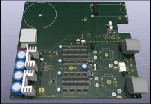
This is the latest release. It is likely that I will no longer develop this project. Only support.
The layout showed good sound quality. Registers 74LVC8T595 with separate output stage power. The power regulator is made according to the classical scheme "precision voltage references + OP + npn". Noise and dynamic performance is better than the LT3042. As resistors, Vishay NOMCT16035001AT1 is used. The active output stage uses shunt voltage regulators. Automatic switching of USB <-> Ethernet inputs.
Full documentation and gerbers will not be published until after successful verification of the first PCB. Unfortunately, COVID has violated the deadlines. Since the full documentation will be available, anyone can independently organize a group buy.
- Home
- Source & Line
- Digital Line Level
- Signalyst DSC1