Doede asked me to start a new thread to discuss output buffers and other PCM1794 output coupling ideas that are outside the scope of his product offering. First, I want to commend Doede for designing and making available a DIY DAC that sounds great with many options and tweaks to make it sound even more amazing.
Here is an excerpt from the results of a comparison of 7 different DDDAC configurations reported in forum post #1468 regarding a single board DAC:
"The surprise of the day was number 4, James his Dac with direct balanced out. This was a nice 2nd place behind number 7. It had most of the openness and detail of 7 and I found it sounding clearly better than the standard 1 and 4 board units. If James changes the I/V resistors to some nice Tantalums than it would be the best dac price wize! Also the changes James has made in the power supply pays off here; well-done James!"
This shows that a tweaked out single board DDDAC1794 can sound amazing providing it has the right output coupling. A single board DDDAC1794 cannot properly drive an output transformer to its full potential. I designed a buffer that provides incredible sq through inexpensive Cinemags. There are other buffer circuit designs to consider as well.
Details on direct output coupling are also welcome here. Maybe someone has an op amp or vacuum tube solution to I/V coupling.
JFET Buffer Circuit
This an explanation of the Buffer Circuit from a post in the DDDAC1794 thread:
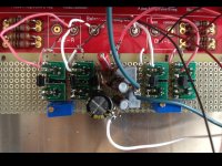
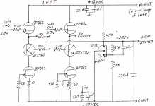
Attached are a schematic and photo of my BF862 JFET buffer. There is almost too much detail. I could hear the valves and mechanical linkage of a bassoon clacking on a Vivaldi recording through my Grado GS1000 headphones – something I have never heard before. The break-in period was UGLY at times and bad recordings are punishing. The best CDs sound amazing.
This Buffer is for the masochistic DIYer unless a PCB is designed for it. It requires testing and matching of BF862 JFETs. A negative power supply is needed. Surface mount components require more care. Nevertheless, a buffer is the only alternative for the person who wants to totally tweak out a single board DDDAC and drive an output transformer without compromising the musical experience. On the positive side, all semiconductors and resistors are inexpensive and available as SOIC-23 surface mount. The BF862 is only available as a SOIC-23. Anyone want to design a surface mount PCB for this buffer? I could provide a set of components with matched BF862s.
The circuit uses the ZTX450 which is used in the highly acclaimed Pearl 2 DIY phono preamp to provide a constant voltage source for the 1st JFET gain stage. The ZTX450 makes the lower BF862 constant current load - more constant, and allows a more standard -12VDC power supply to be used. My prototype uses a mixture of surface mount and standard size components. The TL431 regulates the voltage to the base of the ZTX450s. The 20 ohm pot is used to zero out the voltage offset between the + and – outputs to the transformers.
If the ZTX450s and the TL431 and its associated components are eliminated, you end up with the Nelson Pass B1 direct coupled buffer design which should sound a bit more warm and euphonic. It would be a much simpler circuit.
This an explanation of the Buffer Circuit from a post in the DDDAC1794 thread:
Attached are a schematic and photo of my BF862 JFET buffer. There is almost too much detail. I could hear the valves and mechanical linkage of a bassoon clacking on a Vivaldi recording through my Grado GS1000 headphones – something I have never heard before. The break-in period was UGLY at times and bad recordings are punishing. The best CDs sound amazing.
This Buffer is for the masochistic DIYer unless a PCB is designed for it. It requires testing and matching of BF862 JFETs. A negative power supply is needed. Surface mount components require more care. Nevertheless, a buffer is the only alternative for the person who wants to totally tweak out a single board DDDAC and drive an output transformer without compromising the musical experience. On the positive side, all semiconductors and resistors are inexpensive and available as SOIC-23 surface mount. The BF862 is only available as a SOIC-23. Anyone want to design a surface mount PCB for this buffer? I could provide a set of components with matched BF862s.
The circuit uses the ZTX450 which is used in the highly acclaimed Pearl 2 DIY phono preamp to provide a constant voltage source for the 1st JFET gain stage. The ZTX450 makes the lower BF862 constant current load - more constant, and allows a more standard -12VDC power supply to be used. My prototype uses a mixture of surface mount and standard size components. The TL431 regulates the voltage to the base of the ZTX450s. The 20 ohm pot is used to zero out the voltage offset between the + and – outputs to the transformers.
If the ZTX450s and the TL431 and its associated components are eliminated, you end up with the Nelson Pass B1 direct coupled buffer design which should sound a bit more warm and euphonic. It would be a much simpler circuit.
Attachments
Buffer listeining impressions
Carlsor and I got together a few weeks back to listen to his with buffered Doede dac. Although originally we intended to listen to the addition of his buffer to the output of the dac, by the time we finally were able to get together, calrsor had modified several things in his dac in addition of the buffer. He will report on all the mods in a later post. So, my impressions are of the sound of his fully modified dac, not just the stock dac with the buffer added between the output and the cinemags.
His dac and mine are single board dacs. By coincidende, we both had the same output resistors.
Compared to my version of the dac, which is a stock board with Lundahl trasnformers for output, carlsor's sounded more relaxed and more analog. My stock dac sounded a bit bright in comparison to his. Although the amount of detail was the same between the two dacs, I would say his presentation of the soundstage was more appealing to me. Some of the sounds that were a bit recessed in my stock dac were brought forward by his dac. The bass of his dac seemed to carry a bit more authority than mine too. Overall, his modifications added together resulted in a more musical dac than the stock one I have.
We listened to his dac using his waveio and his home made usb cable. After the dac listening test we replaced the waveio in his dac with my rpi, but no regulator reclocker, just the straight rpi. He didn't like the sound of the rpi, he thought it sounded too digital for his taste. I have to agree with him that it did increase the brightness and harshness of the sound some when compared to the waveio. I however found that it increased the level of detail of the music being played, along with presenting an image of the music that I liked more than the waveio's. I would trade (as I have in my dac) the added brightness-harshness for the increase level of detail and image improvement. But that's why we have different flavor ice cream... not everyone likes the same!
I'm making most of the mods that carlsor made to his dac to mine, except returning to the waveio. They do make Doede's dac sound more relaxed, with a smoother overall sound and changes in the image presentation that are more to my tastes than the stock dac.
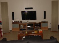
Attached is an image of the listening setup, not state of the art, but I've had it for a very long time so I'm pretty familair with the sound...")
Carlsor and I got together a few weeks back to listen to his with buffered Doede dac. Although originally we intended to listen to the addition of his buffer to the output of the dac, by the time we finally were able to get together, calrsor had modified several things in his dac in addition of the buffer. He will report on all the mods in a later post. So, my impressions are of the sound of his fully modified dac, not just the stock dac with the buffer added between the output and the cinemags.
His dac and mine are single board dacs. By coincidende, we both had the same output resistors.
Compared to my version of the dac, which is a stock board with Lundahl trasnformers for output, carlsor's sounded more relaxed and more analog. My stock dac sounded a bit bright in comparison to his. Although the amount of detail was the same between the two dacs, I would say his presentation of the soundstage was more appealing to me. Some of the sounds that were a bit recessed in my stock dac were brought forward by his dac. The bass of his dac seemed to carry a bit more authority than mine too. Overall, his modifications added together resulted in a more musical dac than the stock one I have.
We listened to his dac using his waveio and his home made usb cable. After the dac listening test we replaced the waveio in his dac with my rpi, but no regulator reclocker, just the straight rpi. He didn't like the sound of the rpi, he thought it sounded too digital for his taste. I have to agree with him that it did increase the brightness and harshness of the sound some when compared to the waveio. I however found that it increased the level of detail of the music being played, along with presenting an image of the music that I liked more than the waveio's. I would trade (as I have in my dac) the added brightness-harshness for the increase level of detail and image improvement. But that's why we have different flavor ice cream... not everyone likes the same!
I'm making most of the mods that carlsor made to his dac to mine, except returning to the waveio. They do make Doede's dac sound more relaxed, with a smoother overall sound and changes in the image presentation that are more to my tastes than the stock dac.
Attached is an image of the listening setup, not state of the art, but I've had it for a very long time so I'm pretty familair with the sound...
Attachments
Hi Frankie,
Thanks for sharing your experience here
The buffer circuit is very interesting... I hope somebody will propose a pcb for it.
Just curious, why you don't use the reclock during the test? Should be very interesting to know your impression with the reclock in place.
Ciao
Enrico
Thanks for sharing your experience here
The buffer circuit is very interesting... I hope somebody will propose a pcb for it.
Just curious, why you don't use the reclock during the test? Should be very interesting to know your impression with the reclock in place.
Ciao
Enrico
Hi Frankie,
Thanks for sharing your experience here
The buffer circuit is very interesting... I hope somebody will propose a pcb for it.
Just curious, why you don't use the reclock during the test? Should be very interesting to know your impression with the reclock in place.
Ciao
Enrico
Hi Enrico. It was a quick test to see what Ross thought about it. Since he did not like it there was no point disassembling my DAC to do further testing with the pi.

Buffer for Cinemags
Yes! That is what I am using. There was a group buy for buffer PCBs by Enrico and I provided the SMD parts including a matched set of JFETs. See http://www.diyaudio.com/forums/digi...ngle-board-pcm1794-nos-dddac.html#post4129467
This Buffer should work on a wide variety DACs
Would something like this also work before the cinemags? jonatan
Yes! That is what I am using. There was a group buy for buffer PCBs by Enrico and I provided the SMD parts including a matched set of JFETs. See http://www.diyaudio.com/forums/digi...ngle-board-pcm1794-nos-dddac.html#post4129467
This Buffer should work on a wide variety DACs
- Status
- This old topic is closed. If you want to reopen this topic, contact a moderator using the "Report Post" button.
- Home
- Source & Line
- Digital Line Level
- DDDAC PCM1794 Output Coupling