The ak4396 is rather old school those days but it's still quite easy to work with. Not being particularly impressed with the PCB implementations I've found on the web, I thought I might try one of my own.
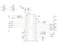
So, would this look right ? It's set in hardware mode ("parallel" mode in the datasheet) for I2S in. Pins listing at the end of the post.
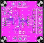
PCB is 5*5cm, I plan a similarly sized pcb for regs, to be fitted on top, to power both the dac and the usb board. The overall idea is to connect it to this usb receiver, which is also 5*5cm. Could make a nicely compact stack.
SMD electrolytics are 22uf oscon SVP, through holes 100uF pana FR. Ferrites l1-3 are 1206 murata ferrites.
Datasheet asks for the power-down to be held down at start-up. Would a simple 10k-100uF delay suffice or is something more elaborate required ?
Critics are welcomed, errors are probably plentiful.
1-dvss: digital gnd, to gndplane
2-dvdd: digital supply
3/5-7: to i2s inputs
4-pdn: power down. Must be kept low at power up. 10k-100uf "slow-start"
8-smute: soft mute, set low to disable
9-dfs0: in auto settings mode, dfs0 is ignored and should be fixed to digital gnd or supply
10-dem0:de-emphasis, set high to disable in parallel mode
11-dem1: de-emphasis, set low to disable in parallel mode
12-dif0: in parallel, pcm mode, should be set to high for 24bits 12s compatible
13-dif1: in parallel, pcm mode, should be set to high for 24bits 12s compatible
14-dif2: in parallel, pcm mode, should be set to low for 24bits 12s compatible
15-ttl: set low for cmos level
16-vrefl: to analog gnd
17-vrefh: to analog supply
18-avdd: analog supply
19-avss: analog gnd
20-24: analog outputs
25-p/s: set high to enable parallel mode
26-tst1: should be left open in parallel mode
27-tst2: in parallel mode, should be tied to digital gnd
28-acks: set high to enable auto settings mode
So, would this look right ? It's set in hardware mode ("parallel" mode in the datasheet) for I2S in. Pins listing at the end of the post.
PCB is 5*5cm, I plan a similarly sized pcb for regs, to be fitted on top, to power both the dac and the usb board. The overall idea is to connect it to this usb receiver, which is also 5*5cm. Could make a nicely compact stack.
SMD electrolytics are 22uf oscon SVP, through holes 100uF pana FR. Ferrites l1-3 are 1206 murata ferrites.
Datasheet asks for the power-down to be held down at start-up. Would a simple 10k-100uF delay suffice or is something more elaborate required ?
Critics are welcomed, errors are probably plentiful.
1-dvss: digital gnd, to gndplane
2-dvdd: digital supply
3/5-7: to i2s inputs
4-pdn: power down. Must be kept low at power up. 10k-100uf "slow-start"
8-smute: soft mute, set low to disable
9-dfs0: in auto settings mode, dfs0 is ignored and should be fixed to digital gnd or supply
10-dem0:de-emphasis, set high to disable in parallel mode
11-dem1: de-emphasis, set low to disable in parallel mode
12-dif0: in parallel, pcm mode, should be set to high for 24bits 12s compatible
13-dif1: in parallel, pcm mode, should be set to high for 24bits 12s compatible
14-dif2: in parallel, pcm mode, should be set to low for 24bits 12s compatible
15-ttl: set low for cmos level
16-vrefl: to analog gnd
17-vrefh: to analog supply
18-avdd: analog supply
19-avss: analog gnd
20-24: analog outputs
25-p/s: set high to enable parallel mode
26-tst1: should be left open in parallel mode
27-tst2: in parallel mode, should be tied to digital gnd
28-acks: set high to enable auto settings mode
Attachments
Where is the MCLK oscillator ?
> Ferrites l1-3 are 1206 murata ferrites.
Go there : SimSurfing
Download ferrite bead spice model
Or look in the simulation forum, I posted a zip.
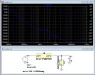
Simulate ferrite with your choice of caps (include ESR/ESL). Check if it makes a LC resonance or not.
> Ferrites l1-3 are 1206 murata ferrites.
Go there : SimSurfing
Download ferrite bead spice model
Or look in the simulation forum, I posted a zip.
Simulate ferrite with your choice of caps (include ESR/ESL). Check if it makes a LC resonance or not.
Where is the MCLK oscillator ?
On the usb board ?
> Ferrites l1-3 are 1206 murata ferrites.
Go there : SimSurfing
Download ferrite bead spice model
Or look in the simulation forum, I posted a zip.
Simulate ferrite with your choice of caps (include ESR/ESL). Check if it makes a LC resonance or not.
Thanks for the tip, going to do that.
It's in the first post, but not very visible, it's true.
Isolated 32bit 384kHz USB to I2S/SPDIF CM6631A PCB - DIYINHK
To link the two board, the idea was to take their ribbon flat cable, cut it to 6cm or so, separate and twist the wires (gnd+ one I2S line each time) and solder them at the dac end.
edit: while I'm at it, here's a first sim of the murata ferrite+os-con. The ceramic cap in // is a 1uF/x7r from the standard ltspice libraries, the other models come from Murata and Panasonic's websites.
Attachments
Last edited:


There's always this one AK4399 32bit Audio DAC PCB kit - DIYINHK But it's quite big with the filter section onboard.


- Status
- This old topic is closed. If you want to reopen this topic, contact a moderator using the "Report Post" button.
- Home
- Source & Line
- Digital Line Level
- AK4396 pcb layout check / question on PDN