Interesting perspective on using the headphone outs as line.
Everything Audio Network: Audiophile Review!Oppo HA-1 DAC/Headphone Amp:“Discrete” Output Nets Sonic Treat
Everything Audio Network: Audiophile Review!Oppo HA-1 DAC/Headphone Amp:“Discrete” Output Nets Sonic Treat
Well, I succeed at least to open my HA1...
Already first mods of this HA1 it will be in place in the next days...
There s not very difficult to open the box, as it may looks like at the first impression. Many screws... This type of screws are not advisable to screw/unscrew many times in the same place...
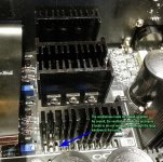
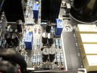
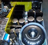
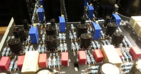
Once inside, one can observe the very carefully assembling on production lines, as for the whole product.
As I have pointed previously, I see the need of some more shielding first of all. There is not easy to reach to the main board, which it host the DAC system. To mod something here, one have to disassemble completely the whole device... Not very comfortable...
I can see that the components (transistors) involved in Class A amplifier, which have to be thermally compensated, where placed very near each other, as it should be, but are not even more close each other, as it have to be also. Actually these components have to be so near as one and single component (if not a double transistor can be found, especially for this function...).
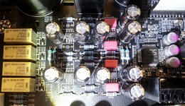
Some words about the main components/opamps used. The I/V & final stages use L4562 for I/V (as we were used with in previous Oppo products). While the final it use a very high quality differential amplifier L49724. Very good figures for this component. Quite satisfied with it so far, but L4562...
The power system for clock and DAC AVCC use TPS7A49. Quite good, but not best...
Headphone it seems to use OPA228 chips, while the preamp input stage it use a very good differential opamp, OPA1632.
I publish here some pictures taken by myself.
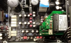
The last picture is one of a soon upcoming and serious mod/upgrade: battery powered clock, using SAW oscillators either an stand alone 108Mhz oscillator or a 216Mhz one with divider.
As this last alternative is already successfully tested, with exceptional results, I think it may be this one as main mod. Also good place inside (actually it fit just fine) for this clock board... Still be clarified yet the dealing with the quite high temperature inside the box...
Already first mods of this HA1 it will be in place in the next days...
There s not very difficult to open the box, as it may looks like at the first impression. Many screws... This type of screws are not advisable to screw/unscrew many times in the same place...
Once inside, one can observe the very carefully assembling on production lines, as for the whole product.
As I have pointed previously, I see the need of some more shielding first of all. There is not easy to reach to the main board, which it host the DAC system. To mod something here, one have to disassemble completely the whole device... Not very comfortable...
I can see that the components (transistors) involved in Class A amplifier, which have to be thermally compensated, where placed very near each other, as it should be, but are not even more close each other, as it have to be also. Actually these components have to be so near as one and single component (if not a double transistor can be found, especially for this function...).
Some words about the main components/opamps used. The I/V & final stages use L4562 for I/V (as we were used with in previous Oppo products). While the final it use a very high quality differential amplifier L49724. Very good figures for this component. Quite satisfied with it so far, but L4562...
The power system for clock and DAC AVCC use TPS7A49. Quite good, but not best...
Headphone it seems to use OPA228 chips, while the preamp input stage it use a very good differential opamp, OPA1632.
I publish here some pictures taken by myself.
The last picture is one of a soon upcoming and serious mod/upgrade: battery powered clock, using SAW oscillators either an stand alone 108Mhz oscillator or a 216Mhz one with divider.
As this last alternative is already successfully tested, with exceptional results, I think it may be this one as main mod. Also good place inside (actually it fit just fine) for this clock board... Still be clarified yet the dealing with the quite high temperature inside the box...
Attachments
Last edited:
Well, I succeed at least to open my HA1...
Already first mods of this HA1 it will be in place in the next days...
There s not very difficult to open the box, as it may looks like at the first impression. Many screws... This type of screws are not advisable to screw/unscrew many times in the same place...
Once inside, one can observe the very carefully assembling on production lines, as for the whole product.
As I have pointed previously, I see the need of some more shielding first of all. There is not easy to reach to the main board, which it host the DAC system. To mod something here, one have to disassemble completely the whole device... Not very comfortable...
I can see that the components (transistors) involved in Class A amplifier, which have to be thermally compensated, where placed very near each other, as it should be, but are not even more close each other, as it have to be also. Actually these components have to be so near as one and single component (if not a double transistor can be found, especially for this function...).
Some words about the main components/opamps used. The I/V & final stages use L4562 for I/V (as we were used with in previous Oppo products). While the final it use a very high quality differential amplifier L49724. Very good figures for this component. Quite satisfied with it so far, but L4562...
The power system for clock and DAC AVCC use TPS7A49. Quite good, but not best...
Headphone it seems to use OPA228 chips, while the preamp input stage it use a very good differential opamp, OPA1632.
I publish here some pictures taken by myself.
The last picture is one of a soon upcoming and serious mod/upgrade: battery powered clock, using SAW oscillators either an stand alone 108Mhz oscillator or a 216Mhz one with divider.
As this last alternative is already successfully tested, with exceptional results, I think it may be this one as main mod. Also good place inside (actually it fit just fine) for this clock board... Still be clarified yet the dealing with the quite high temperature inside the box...
Thanks for sharing your work here. I'll be waiting for your mod updates!
Well, well, some first/initial mods are in place for this Oppo device too...
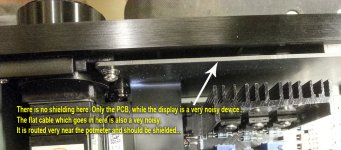
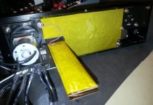
There are some pictures here, and there is a mod mainly about shielding some part of the device.
I used some special EMI shielding material, but other material may be appropriate for this task. As my material is electrical conductive, I cover it with heat resistant isolating foil.
The shielding of the toroid is a dedicated material one, but at least some steel foil is also good.
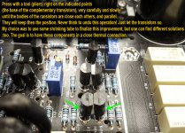
There is also an improvement for the complementary transistors involved in Class A amplifier stage. In the ideal situation, these transistors it have to be together under the the same temperature variation. The best way is to have it both on the same silicium slice (for a price...). Or as it is. but close as possible to each other. I think this pictured here, is the way to do it to get these components in close thermal contact.
Some words about the ventilation system in Oppo design.
In my opinion, this design is a quite low efficient one, when to remove the high thermal energy which a Class A amplifier develop.
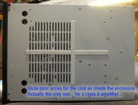
As you can see in original design, there are some holes in a enough small area on the lower side of the enclosure. The holes in the upper base PCB are even less as number and dimensions. The result: poor ventilation and heating up the entire enclosure and its content.
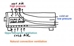
A better solution suggested here to Oppo designers (for the HA-2...) is to let somehow open the back of the enclosure. This enclosure is hopefully very similar to a tube, when the end of it is open. There is a known physical phenomenon which consist in increasing the pressure into a tube (when pressure differences occur at tube`s ends) as the length of the tube increase. The quite high temperature differences create here pressure differences inside this tube (the enclosure). Heaving the back end open or designed for air access, there is a natural created and a very efficient ventilation, when the hot air push up and such the cold air mainly from the best access opening. The quite long tube create an enough pressure to produce an efficient air flow, when the back of the box is open or is air access able. I made a sketch to illustrate the idea. For sure a physician it may describe better what is all about...
The holes in the lower side of the enclosure are usefully to initiate the air flow, when the temperature differences are low, but when the temperature increase, the pressure increase and the cold air will flow inn in high quantity from the back side of the tube/enclosure. The ventilation become then very efficient and natural.
I just removed the back panel of the box, and then the enclosure shown at once different temperature zones. The back side still quite cold, while the upper window, become even more hot. So it have to be when the hot air is efficient evacuated.
The negative side of this mod is no any mechanical support for the connections of the amplifier on its back end. But if this device is integrated in a very stable system, then the back panel can be removed to create a better ventilation inside the enclosure.
A separation between the hot areas and the cold ones inside the box it can improve even more the air flow, and lower the temperature for some important inside components.
So, what it may be the solution to have a mechanical stable system, and a better ventilation? It should be designed a special grill for the back end of the enclosure, instead of the existent back panel. That grill it should sustain well enough the connections back, and it will provide air access for an more efficient ventilation.
There are some pictures here, and there is a mod mainly about shielding some part of the device.
I used some special EMI shielding material, but other material may be appropriate for this task. As my material is electrical conductive, I cover it with heat resistant isolating foil.
The shielding of the toroid is a dedicated material one, but at least some steel foil is also good.
There is also an improvement for the complementary transistors involved in Class A amplifier stage. In the ideal situation, these transistors it have to be together under the the same temperature variation. The best way is to have it both on the same silicium slice (for a price...). Or as it is. but close as possible to each other. I think this pictured here, is the way to do it to get these components in close thermal contact.
Some words about the ventilation system in Oppo design.
In my opinion, this design is a quite low efficient one, when to remove the high thermal energy which a Class A amplifier develop.
As you can see in original design, there are some holes in a enough small area on the lower side of the enclosure. The holes in the upper base PCB are even less as number and dimensions. The result: poor ventilation and heating up the entire enclosure and its content.
A better solution suggested here to Oppo designers (for the HA-2...) is to let somehow open the back of the enclosure. This enclosure is hopefully very similar to a tube, when the end of it is open. There is a known physical phenomenon which consist in increasing the pressure into a tube (when pressure differences occur at tube`s ends) as the length of the tube increase. The quite high temperature differences create here pressure differences inside this tube (the enclosure). Heaving the back end open or designed for air access, there is a natural created and a very efficient ventilation, when the hot air push up and such the cold air mainly from the best access opening. The quite long tube create an enough pressure to produce an efficient air flow, when the back of the box is open or is air access able. I made a sketch to illustrate the idea. For sure a physician it may describe better what is all about...
The holes in the lower side of the enclosure are usefully to initiate the air flow, when the temperature differences are low, but when the temperature increase, the pressure increase and the cold air will flow inn in high quantity from the back side of the tube/enclosure. The ventilation become then very efficient and natural.
I just removed the back panel of the box, and then the enclosure shown at once different temperature zones. The back side still quite cold, while the upper window, become even more hot. So it have to be when the hot air is efficient evacuated.
The negative side of this mod is no any mechanical support for the connections of the amplifier on its back end. But if this device is integrated in a very stable system, then the back panel can be removed to create a better ventilation inside the enclosure.
A separation between the hot areas and the cold ones inside the box it can improve even more the air flow, and lower the temperature for some important inside components.
So, what it may be the solution to have a mechanical stable system, and a better ventilation? It should be designed a special grill for the back end of the enclosure, instead of the existent back panel. That grill it should sustain well enough the connections back, and it will provide air access for an more efficient ventilation.
Attachments
-
 ventilation improvement.jpg174.8 KB · Views: 234
 -
 ventilation - back side.jpg447.4 KB · Views: 229
 -
 all the shieldings mod-improvement.jpg627.7 KB · Views: 225
 -
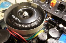 shielding the toroid.jpg599.9 KB · Views: 223
 -
 Shielding the display and its cable.jpg643.6 KB · Views: 223
 -
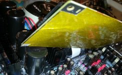 shielding the back side of the digital board.jpg524.6 KB · Views: 267
 -
 classA-2.jpg750.5 KB · Views: 235
 -
 complementary transistors.jpg513.3 KB · Views: 233
Last edited:
I found out some more about the preamp output stage. I can confirm that it have nothing to do with the Class A for headphone. There are two different output stages. They have in common the same signal in each`s inputs.
The preamp outputs (balanced/unbalanced) are AC coupled. There are 100µ AC isolating caps on both differential and unbalanced outputs. There is used for balanced OPA1632, and for unbalanced L4562.
I have removed the AC coupling for unbalanced out. Direct coupling. Improved the decoupling caps on L4562 power rails, to 3000µ. The offset measured at the direct coupled unbalanced output is 0,8 - 1mV.
This mod opened more the sound out of the device.
Enough unclear the Oppo`s reasons to chose the AC coupling...
I found out some more about the preamp output stage. I can confirm that it have nothing to do with the Class A for headphone. There are two different output stages. They have in common the same signal in each`s inputs.
The preamp outputs (balanced/unbalanced) are AC coupled. There are 100µ AC isolating caps on both differential and unbalanced outputs. There is used for balanced OPA1632, and for unbalanced L4562.
I have removed the AC coupling for unbalanced out. Direct coupling. Improved the decoupling caps on L4562 power rails, to 3000µ. The offset measured at the direct coupled unbalanced output is 0,8 - 1mV.
This mod opened more the sound out of the device.
Enough unclear the Oppo`s reasons to chose the AC coupling...
Can you confirm how the headphone input is coupled with the DAC output --- is it similarly AC coupled with coupling cap, or servo circuit using opamp --- or DC coupled?
Thanks for sharing your great work and ideas.
Yes, I can... Unfortunately...
The headphone amplifier is AC coupled. !00µ in between its differential pre-amplifier stage (L49724), and the power headphone class A stage.
All these AC separation caps should be at least non polarised type. A chepear solution is to use a pair of polarised caps. No any such approach in Oppo`s products...
As it still unknown yet what kind of circuits are used for class A stage, one could not just bypass these caps. Until one find out details (not so probable...), these caps should be there in place. But improvements can however be.
The AC coupling are placed in HA-1 on its (preamp) outputs (balanced/unbalanced), and at input for headphone amp. As I could see so far...
There is a serious problem with the heat developed by this product (as it is). It may be difficult to use it in summer times, or in tropical areas... I mean, one can use it, but it will not last for long time...
Last edited:
Yes, I can... Unfortunately...
The headphone amplifier is AC coupled. !00µ in between its differential pre-amplifier stage (L49724), and the power headphone class A stage.
All these AC separation caps should be at least non polarised type. A chepear solution is to use a pair of polarised caps. No any such approach in Oppo`s products...
As it still unknown yet what kind of circuits are used for class A stage, one could not just bypass these caps. Until one find out details (not so probable...), these caps should be there in place. But improvements can however be.
The AC coupling are placed in HA-1 on its (preamp) outputs (balanced/unbalanced), and at input for headphone amp. As I could see so far...
There is a serious problem with the heat developed by this product (as it is). It may be difficult to use it in summer times, or in tropical areas... I mean, one can use it, but it will not last for long time...
what is the value and make/model of the electrolytic used? Is it at least a black gate or an oppo proprietary type? Maybe bypass at a minimum with a film type? What do you you think? Do you think servo circuits are just too expensive? Somehow they were able to get tremendous bass response regardless.
The Headphone amp still sounds fabulous....so they did a good job with the design in many ways... but based on your findings...room for improvement
I measured more distortion (some, small, only on the HP slope where the Cap is still dropping some V) in R,L channel Nichicon Gold, "Audiophile " DC blocking, signal Caps than the ordinary blue case electros used in the surround channels of a Sony SACD player
film bypass will do squat down there, non/bipolar Al electros are a likely measurable distortion performance upgrade - if still inaudible if you really did proper blind testing
film bypass will do squat down there, non/bipolar Al electros are a likely measurable distortion performance upgrade - if still inaudible if you really did proper blind testing
Last edited:
I measured more distortion (some, small, only on the HP slope where the Cap is still dropping some V) in R,L channel Nichicon Gold, "Audiophile " DC blocking, signal Caps than the ordinary blue case electros used in the surround channels of a Sony SACD player
film bypass will do squat down there, non/bipolar Al electros are a likely measurable distortion performance upgrade - if still inaudible if you really did proper blind testing
Thanks jcx, I would like to know what part is used for DC blocking to the headamp -- and ideas to improve on this specifically.
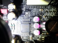
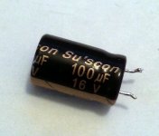
This is the cap type Oppo use as DC blocking in HA-1.
To improve the parameters/sound, one should increase the value of the cap, but not opposite... The higher its value, the better the results. But when is to big the capacity, it can occur some side effects for the stage after this cap. So, a reasonable compromise may leads to a good result. Best results: without (but we do not know exactly how Oppo designed the class A amplifier, and the implications of DC coupling in this place).
At least this cap should be bipolar, as all the DC blocking caps, rated for a higher working tension. This it may be another improvement here. Paralleled with a good quality, small film cap, another one...
The output stage caps can be safe removed, but verify if your amplifier it feels comfortable with DC coupling. Offset on outputs is 1mV.
Attachments
Thanks Coris... that looks rather horrid.
If any brave soul wants to try and completely remove it from output --- and wants to see if the headamp becomes dead or is just fine... let us know No capacitor sounds better than none at all.
But in absence of DC coupling the outputs, if you have any particular bipolar 100uf in mind that is the best to use -- please post so we can consider trying (I will)
Any recommendation for specific film capacitor in mind for bypassing? If so, which brand and value? Polystyrene, etc?
If any brave soul wants to try and completely remove it from output --- and wants to see if the headamp becomes dead or is just fine... let us know
No capacitor sounds better than none at all. But in absence of DC coupling the outputs, if you have any particular bipolar 100uf in mind that is the best to use -- please post so we can consider trying (I will
)Any recommendation for specific film capacitor in mind for bypassing? If so, which brand and value? Polystyrene, etc?
Any film capacitor of quite small dimensions it may be good. I used SMD type. Value under 0,1µ.
Electrolytic caps can be bipolar if one solder together (serial) two of such - to - or + to +.
The rest of the two legs of the same polarity goes in place on PCB. The advantage of such configuration is half of needed voltage rate for each cap, and reduced dimensions. So (serial), 1000µ/10v + |1000µ/10v = 500µ/20v
And not to forget: short legs as possible when soldered in place.
Last edited:
Any film capacitor of quite small dimensions it may be good. I used SMD type. Value under 0,1µ.
Electrolytic caps can be bipolar if one solder together (serial) two of such - to - or + to +.
The rest of the two legs of the same polarity goes in place on PCB. The advantage of such configuration is half of needed voltage rate for each cap, and reduced dimensions. So (serial), 1000µ/10v + |1000µ/10v = 500µ/20v
And not to forget: short legs as possible when soldered in place.
Thanks Coris.... are you making small changes and listening or larger ones first. Like are you changing the coupling cap, listening to the improvement, then adding the bypass cap --- then listening again? Curious to understand what changes are attributed to what sonic changes you hear.
Now that you are working on this significantly....other than the heat "issues" are you still positive on the sound and design of the oppo?
Thanks very much
why does this bad info still persist - read Bateman "Capacitor Sound" articles
buy Bipolar electros - have full thickness oxide grown on both foils - measures lower distortion than the outdated "back-to-back" polar electrolytics, takes less space too
One should of course use the right components... when one it have it. When not, one can try/experiment with existent ones. If the results are encouraging, then switch to the right way to do it...
That`s the philosophy of my previous post...
Thanks Coris.... are you making small changes and listening or larger ones first. Like are you changing the coupling cap, listening to the improvement, then adding the bypass cap --- then listening again? Curious to understand what changes are attributed to what sonic changes you hear.
Now that you are working on this significantly....other than the heat "issues" are you still positive on the sound and design of the oppo?
Thanks very much
You know is quite a pain to mount/unmounted this device, to test so after any small modification. I will do some preliminary mods, then I will test the sound, and try to have some conclusions.
I`m in the working phase for moment...
The HA-1 have some qualities as it is. This is obvious enough. It can provide a sound scene the other Oppo product couldn`t.
Even though, I am not quite satisfied with what i got/get, especially after listening to my modded BDP105.
I found the sound of HA-1 not as open as it should. Do not full out the room (I did not used the headphones yet). The sound it not have the volume I know it should have. This is my opinion.
In HA-1 Oppo use better opamps than in the players. It use also better regulators. But it use the same kind of caps (values), in a similar design as in players... The AC isolation is a way to do it and it may not be just as negative, but one could use large capacities caps for this AC/DC separation. Is just as simple... and it improve the signal quality, and it may not be so expensive...
I saw the headphone traces going on the PCB from one corner of it to another... Very long traces on the board... I`m not very happy with this...
But the worst of all with the design of this device is its physical/mechanical part (ventilation), or the managing with the important heat developed inside the box. This aspect is quite bad.
I just wonder how it was the environment when Oppo did its measurements...
I had the device in function for a while, without its nice enclosure in place. So, just opened in the air. The Class A stage spread it its heat out in the free air. I was very surprised to find out the the DAC area it was just very hot after one-two hours in use in a 26 dg C room temperature (in a hot Norwegian summer time...). I just wonder what it may be the temperature of the DAC area when the enclosure is completely closed as Oppo designed, and the whole heat from Class A heat sinks is spread inside the enclosure... I wonder even more about how long it may last a such device in such functioning conditions...
Last edited:
Maybe too much knowledge, in this case, is dangerous for us Sorry coris you are not entirely happy with it.
If you are game --- I do think your feelings of it may change somewhat with its use as a headphone amp. It sounds markedly better than others I have compared it to (at higher and lower its pricepoint). It also sounds much better after being on for a while... maybe that is because of all those crappy capacitors in the system But this can be a problem because it runs so hot... This coupled with its handling of DSD, nice remote make it quite good in total. But as an external DAC....I am not sure I would want all this "baggage" for less than optimal performance compared to alternatives.
Sorry coris you are not entirely happy with it. If you are game --- I do think your feelings of it may change somewhat with its use as a headphone amp. It sounds markedly better than others I have compared it to (at higher and lower its pricepoint). It also sounds much better after being on for a while... maybe that is because of all those crappy capacitors in the system
But this can be a problem because it runs so hot... This coupled with its handling of DSD, nice remote make it quite good in total. But as an external DAC....I am not sure I would want all this "baggage" for less than optimal performance compared to alternatives.Yah... It may be my problem this... I`m not entirely happy with something... I think one can always get a little bit more out of something...
I have observed something strange about these caps. The 100µ/16v cap used for AC/DC isolation is bigger as dimensions than a 220µ/25v used for filtering in all the device. Almost twice. The dimensions of these components it have to be just opposite. It may be 100µ a special (customized) construction one? It may be a bipolar one? As usually these bipolar caps are bigger than the polarised ones for same capacities... But if so, why they are marked with +/-?
Oppo`s secret components...
- Status
- This old topic is closed. If you want to reopen this topic, contact a moderator using the "Report Post" button.
- Home
- Source & Line
- Digital Line Level
- OPPO`s HA-1 Headphone amplifier - discussions, upgrading, mods...