I usually use R2R as "generic" name for classic multibit ladder architectures.
Not all multibit DACs are ladder architecture. R2R refers to ladder.
But R2R seems only to be specifically mentioned in datasheets for DACs like PCM1704, etc.
That's a classic example of an R2R.
Also, MSB Tech, Mother-of-Tone, HyperPhysics seem to limit discussion of DACs arch. to
R2R/ladder, D-S, and "summing amplifier".
Last time I looked at Charles' (Mother of Tone) site, he wasn't clear about the difference between R2R and multibit so a lot of confusion exists for sure.
In an earlier DIY topical discussion, you also refereed to another type (arch.), segmented current sources (with or w/o DEM), putatively used in TDA1541
Is this what TDA1543 and TDA1545 use, too?
For sure with 1545, but its not totally clear with 1543. Probably the 'passive divider' in the latter is done with transistors but no DEM (hence use of 'passive') rather than 'passive' referring to passive components (resistors).
Also, is there a White Paper on Philips use of segmented current sources? It does not seem to be mentioned all that often in datasheets, etc.
There's a paper about the internal design of TDA1541A and specifically dynamic element matching, written by Rudy van de Plassche. Google's your friend.
Incidentally what are the flaws you see with CD?
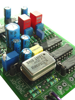
Double Crown TDA1541a
...Double Crown TDA1541a...with interchangeable PMD100 or SAA7220B ...
in a Magnavox CD-650 + external PSU project...
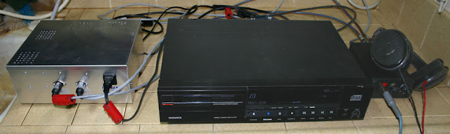
left: External PS
center: heavily modified CD-650
right: DIY headphone amp; Sennheiser HD-650

External BALANCED-pwr PSU: Three DIN V_dc out (two on front; one rear). 120VAC (balanced pwr out); Corcom EMI/EMF filter; Inrush current suppression (soft start)
Philips (Magnavox) CD-650 (1986 model); Kwack clock; DEM reclocking for TDA1541A; inter-IC re-clocking; double-Flea (far upper right) for certain logic ckts. Output is Prometheus/Pass design.
And then, about a year ago, I bypassed the CDM (transport) and added I2S-fed QLS-HiFI QA-350 wav device ... and sonics improved quite significantly ...
CDs/CDPs (like vinyl) are way too labor-intensive, high-maint. ... and I miss week-long playlists.
The project above was a one-time/non-serious thing ...proof-of-concept/personal challenge/yada-yada 🙄 ... dumbed-down stuff that a sh*t-plumber could solder up on weekends, or when plunge jobs were slow. Now, all I really need -- DIY or ready-made-from China -- is portable gear that feeds off a Tablet or iPhone.
BTW: Also experimented with some recent Musical Fidelity DACs, Asus Xonar XT soundcard, etc. Believe it or not, 95% of my day-to-day listening is via sub-optimal PC audio or iPod Touch. ALL my listening is headphones/IEMs-only. Haven't used loudspeakers in years!
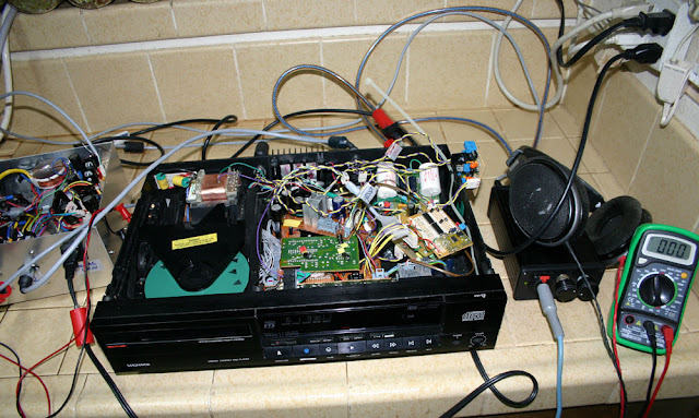
Look at the mess I made a few years ago.. I call it the "Magnavox Mess."Incidentally what are the flaws you see with CD?
...Double Crown TDA1541a...with interchangeable PMD100 or SAA7220B ...
in a Magnavox CD-650 + external PSU project...
left: External PS
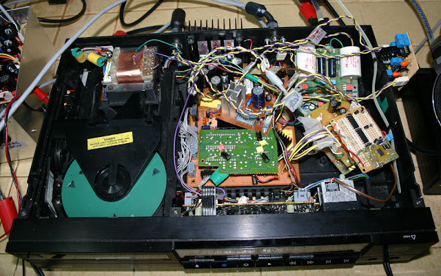
center: heavily modified CD-650
right: DIY headphone amp; Sennheiser HD-650
External BALANCED-pwr PSU: Three DIN V_dc out (two on front; one rear). 120VAC (balanced pwr out); Corcom EMI/EMF filter; Inrush current suppression (soft start)
Philips (Magnavox) CD-650 (1986 model); Kwack clock; DEM reclocking for TDA1541A; inter-IC re-clocking; double-Flea (far upper right) for certain logic ckts. Output is Prometheus/Pass design.
And then, about a year ago, I bypassed the CDM (transport) and added I2S-fed QLS-HiFI QA-350 wav device ... and sonics improved quite significantly ...
CDs/CDPs (like vinyl) are way too labor-intensive, high-maint. ... and I miss week-long playlists.
The project above was a one-time/non-serious thing ...proof-of-concept/personal challenge/yada-yada 🙄 ... dumbed-down stuff that a sh*t-plumber could solder up on weekends, or when plunge jobs were slow. Now, all I really need -- DIY or ready-made-from China -- is portable gear that feeds off a Tablet or iPhone.
BTW: Also experimented with some recent Musical Fidelity DACs, Asus Xonar XT soundcard, etc. Believe it or not, 95% of my day-to-day listening is via sub-optimal PC audio or iPod Touch. ALL my listening is headphones/IEMs-only. Haven't used loudspeakers in years!
Last edited:
Looking at the timing diag. in the TDA1545A datasheet (fig. 6), it is shown that MSB (I assume this is bit #1 of the usual 1 [MSB] to 16 [LSB]), is kept ON for several clock cycles before shifting to bits 2-16.
Why did EIAJ chose this "strategy"?
Why did EIAJ chose this "strategy"?
Actually I think that's just a strange representation by Philips rather than anything from EIAJ. In my understanding the bits to the left of the 'real' MSB are all don't care. They'll get ignored. Everything becomes much simpler conceptually with a 32fs clock.
EIAJ advantages?
As a transmission format, I wonder if EIAJ has certain advantages -- maybe when used concomitantly within "continuous calibration" architecture?
The TDA1545A, with its EIAJ input, has a kind of cult following. However, TDA1545A's near-twin brother TDA1387T (same continuous calibration architecture as 1545A) almost gets no mention -- it is I2S.
Why did Japan go non-standard here?Actually I think that's just a strange representation by Philips rather than anything from EIAJ. In my understanding the bits to the left of the 'real' MSB are all don't care. They'll get ignored. Everything becomes much simpler conceptually with a 32fs clock.
As a transmission format, I wonder if EIAJ has certain advantages -- maybe when used concomitantly within "continuous calibration" architecture?
The TDA1545A, with its EIAJ input, has a kind of cult following. However, TDA1545A's near-twin brother TDA1387T (same continuous calibration architecture as 1545A) almost gets no mention -- it is I2S.
Last edited:
Why do you call EIAJ 'non-standard' ? Just because it differs from I2S? In which case what makes I2S 'standard' ?
I do designs with both TDA1387 and TDA1545A. I do prefer the 1545A for a couple of reasons - it draws about half the power of the 1387 and it can deliver double the current. If only the 1545 (original I2S version) was still available, that'd be the best of both worlds. TDA1387's wider output voltage compliance doesn't convey any advantages to me as I like a balanced architecture.
I do designs with both TDA1387 and TDA1545A. I do prefer the 1545A for a couple of reasons - it draws about half the power of the 1387 and it can deliver double the current. If only the 1545 (original I2S version) was still available, that'd be the best of both worlds. TDA1387's wider output voltage compliance doesn't convey any advantages to me as I like a balanced architecture.
The TDA1545A is a good, lil' DAC. Only wish there was a simpler way to convert I2S to EIAJ.
I still haven't figured out why I can't get that two-chip ckt to work.
I still haven't figured out why I can't get that two-chip ckt to work.
Its pretty straightforward to see why that circuit can't work - the original premise is incorrect. He says 'invert WS and delay the data by 7 clocks'. Well the first bit's right but the second is obviously wrong - within a 32 bit field, the difference between left justified (I2S) and right justified (EIAJ) will be 16 bit times. Subtract one for I2S's 1 bit advanced WS and you need 15 bit time adjustment. Add on another 8bit register to accomplish that and it might just fly.
Universal shifter
You lost me ... are you saying a 3-chip design might work?
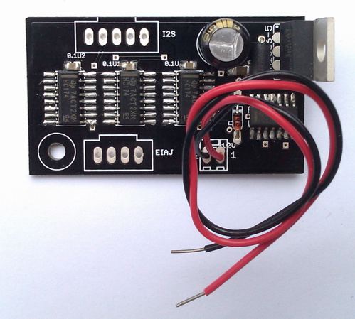
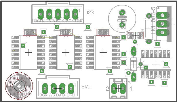
The one in your Blog uses more than that as does the WORKING -- but messy -- "Universal Shifter" ckt I'm using:
(note that only DATA line is shifted, seven times. BCK and WS are fed to DACs BCK and WS pins unchanged).

Add on another 8bit register to accomplish that and it might just fly.
You lost me ... are you saying a 3-chip design might work?
The one in your Blog uses more than that as does the WORKING -- but messy -- "Universal Shifter" ckt I'm using:
(note that only DATA line is shifted, seven times. BCK and WS are fed to DACs BCK and WS pins unchanged).
Last edited:
The circuit on my blog isn't intended to do I2S to EIAJ - it just happens that such a conversion becomes almost trivial when the frame size is 16bits. Reduction of the frame size to 16bits is the purpose of my circuit.
Yes I reckon a 3 chip solution has to be worth a shot. Doing it with ALS374 latches though is messy because of having to wire so many ins to outs. Why not just use shift regs? I use HC595s because they're dirt-cheap here but they have another internal register which makes the circuit a little more difficult to design. 74HC164s would be a better choice.
Yes I reckon a 3 chip solution has to be worth a shot. Doing it with ALS374 latches though is messy because of having to wire so many ins to outs. Why not just use shift regs? I use HC595s because they're dirt-cheap here but they have another internal register which makes the circuit a little more difficult to design. 74HC164s would be a better choice.
Diyparadise does it with three flip-flops and a buffer:
(it's called Black Crowe)
I think the F-F's are HC174's. Dunno what the buffer IC is (any clues?)
And how are the F-F's wired? Two ins/outs per IC ... or other???
(it's called Black Crowe)
I think the F-F's are HC174's. Dunno what the buffer IC is (any clues?)
And how are the F-F's wired? Two ins/outs per IC ... or other???
Last edited:
{Actually, in the schematic posted the data is shifted 48 bit-times.}(note that only DATA line is shifted, seven times. BCK and WS are fed to DACs BCK and WS pins unchanged).
Without doubt, the most important signal in any D/A converter is the sample clock. For most serial input DAC chips, the bit clock serves as the sample clock. For that reason, BCLK should be unpolluted. In your universal shifter, BCLK is driving six loads in addition to the DAC chip. Each load adds about 5pf to the BCLK net. The additional capacitance slows the clock signal and extends the time the signal is in the zero-to-one transition zone. That increases the uncertainty of the exact time the DAC chip recognizes the clock edge and that means jitter.
But that’s not all. The HC164 outputs change immediately after each clock edge. There are 48 output pins, about half of which will change state with each clock. CMOS logic consumes very little power except when it is changing state. Then it takes a big gulp of current and creates a lot of noise and ground bounce. Most of those 48 output pins are unused and each unterminated pin is a little antenna radiating RFI into the surrounding circuit. All that is happening during the rising edge of BCLK, the very moment the DAC chip is doing its most important job.
Your Universal Shifter is more like a Universal Noise and Jitter Generator. Don’t feel bad. All the diyaudio experts do the same thing.
http://www.diyaudio.com/forums/digi...ilding-ultimate-nos-dac-using-tda1541a-5.html
DDDAC 1794 NOS DAC - Non Oversampling DAC with PCM1794 - no digital filter - modular design DIY DAC for high resolution audio 192/24 192kHz 24bit
There is no reason the I2S to EIAJ conversion cannot be done with as few as three CMOS chips while adding no additional loads to BCLK, preserving the timing relationship between BCLK and DATA (something the diyaudio experts don’t do) and not polluting the rising edge of BCLK.
Exam is open-book ... but show your work--you won't be graded on a curve!
So ... where's YOUR schematic 😉There is no reason the I2S to EIAJ conversion cannot be done with as few as three CMOS chips ....
I don't feel bad and the Universal Shifter is not my design. As far as noise in I2S<-->EIAJ conversion ... I speculated on this very issue some time back in the original EIAJ-I2S- and Vice Versa thread.Your Universal Shifter is more like a Universal Noise and Jitter Generator. Don’t feel bad. All the diyaudio experts do the same thing.
Last edited:
So ... where's YOUR schematic 😉
You might not get one - this from Tam Lin's comments on my blog :
Schematics are inadequate for digital circuits. There is no value to the pictorial representation. Most of the symbols are rectangles.... I don't use schematics.
But he gave me one, even though I didn't ask for it 😀
You might not get one - this from Tam Lin's comments on my blog :
Schematics are inadequate for digital circuits. There is no value to the pictorial representation. Most of the symbols are rectangles.... I don't use schematics.
But he gave me one, even though I didn't ask for it 😀
Unless an indiv. can back up their claims by posting a schematic (and a working one at that), that indiv. is ALL TALK.
But since were only talking about a putatively, now-simple (3 or 4- chip) ckt, just a few words (or simple syntax) will work, too, such as ...
IC1 (HC174): DATA to 1D; 1Q to 2D; 2Q to ...
IC2 (HC174): ...1Q to 2D; 2Q to ...
IC3 (HC174): [Fill in Lin]
...
IC4 (HC125; buffer): ... to DAC!!
And, no need to CAD ... you can just Google Image up ...

Or why not Photoshop a photo...

Uh...but those aftermarket clocks which have all sorts of buffering and "re-clocking" (even asynchronous!!) have gobs of "polluting" buffers and F-Fs and latches ... and yet they improve sonics AND metrics ....For that reason, BCLK should be unpolluted.
Uh...but those aftermarket clocks which have all sorts of buffering and "re-clocking" (even asynchronous!!) have gobs of "polluting" buffers and F-Fs and latches ... and yet they improve sonics AND metrics ....
It seems everything improves sonics. It’s amazing how audiophiles can hear the tiniest things that can’t be explained or measured but not hear the big things that can be explained and measured. You seem to be happy with your universal noise generator but have you noticed that it reduces the dynamic range by 6dB?
BTW, the two diyaudio experts I alluded to above were champions of asynchronous reclocking and wrote extensively how wonderful it was. Of course, they were both selling stuff that used async reclocking. If async reclocking leads to improved sonics, why isn’t it done anymore? Maybe it was just a fad and audiophiles hear what they want to hear. After the bandwagon passes they don’t hear the improvements anymore. In the beginning, ecdesigns didn’t have anything good to say about async reclocking (see post #1 in that thread). Later he got religion and adopted async reclocking in his adaptive USB DACs and reclocked with the USB clock. At the time he didn’t realize the USB clock was not related to the sample clock in any way.
I am a programmer, now retired, who spent many years working for startups in the mainframe computer business. I was surrounded by EEs. The most discussed topics were signal integrity and clock distribution. I may have missed some of the details but I vividly remember the concepts and how they are applied. I’ll save the lecture because you diyaudio experts know it all in spite of never reading datasheets. From his initial question it is obvious hollowman never read the CS8412 data sheet and abraxalito never read the I2S bus specification because he thinks it is good practice to latch the data bit on the falling edge of BCLK.
abraxalito is right; I don’t use schematics - for my own work. Because you diyaudio experts are unable to assimilate new ways of looking at digital circuits I have to resort to schematics to communicate, and that's a lost cause. Here are six I2S to EIAJ conversion circuits that minimize pollution of BCLK and preserve signal phase relationships. CMOS variations optimized for minimum chip count. LVCMOS variations optimized for performance.
P.S. I just remembered; asynchronous reclocking is used today in USB audio. Asynchronous USB audio is a tough nut to crack. To get in the game you have to either:
1) Do your own 'clean room' implementation of the USB endpoint and driver.
2) Pay a licensing fee someone who has already done the hard work.
3) Cheat and simply reclock the output of an adaptive USB receiver.
You'd be suprised how may USB DACs makers chose option 3. The audiophile customer doesn't know the difference. All three are advertised to be the real thing and they look the same; a big gate array chip flanked by two ultra-low jitter oscillators. All three get great reviews from the golden ears but one is a fraud.
P.P.S. Years ago, when I was living in Berkeley, CA, I got a call from KQED, the PBS station in San Francisco. They wanted to borrow a harpsichord for a Christmas concert. I said, I can lend you an instrument, when is the concert? They said, tonight. (One of my hobbies at the time was making harpsichords and KQED learned about me from KPFA, the Pacifica radio station in Berkeley. Earlier that year I made a harpsichord for KPFA.) I got to the TV station literally moments before air time. There was no time for a proper tuning so I resorted to a quickie with a strobe tuner. That was just as well because the studio was noisy with TV station techs setting up and the singers warming-up their voices. I had just finished and put my tools away when the choir master came in. He sat down at the harpsichord and played a few chords. Lovely instrument, he said, you used an electronic tuner, didn’t you?
How did he know? Do any of you golden-eared, diyaudio experts think you could tell the difference? Have you ever wondered why so few musicians care about high-end audio? Most musicians are very sensitive to pitch. Audiophiles are not, yet pitch is one of the most important attributes of music! The oft-stated axiom in this forum is that low jitter is the most important oscillator spec, not absolute accuracy or stability. OK, if jitter is bad, then why would any audiophile think asynchronous re-clocking was good? It always results in dropped or duplicate samples and that, by definition, is deterministic jitter. It also creates pitch instability, much like wow in a tape deck or turntable. First generation CD Players, while often panned by audio snobs, were praised by musicians. Why? Because they had much better pitch accuracy and stability than any tape deck or turntable.
The difference between tuning by ear and with electronics is a very interesting subject that parallels the subjective vs.objective dichotomy in audio. With an electronic tuner, each string is tuned to the exact frequency as defined by temperament used by the tuner; usually equal temperament. When tuning by ear, each string is tuned in accordance with how it relates to every other string to enhance the best qualities of the chosen temperament.
I’m outta here. Gotta work on the PCB layout of my magnum opus; a DAC that includes the features I think important in good digital audio design.
Attachments


abraxalito never read the I2S bus specification because he thinks it is good practice to latch the data bit on the falling edge of BCLK.
Seeing as I got a mention in dispatches I'll just point out that Tam Lin's mind reading skills really suck. Latching on falling edge of BCLK has worked reliably so far for me.
I've built that three-74HC174 converter and have stereo signal (i.e., music, audio, whatever) -- on the L/R OUT of the DAC chip -- but very distorted: sounds like pink noise+normal signal.
Also, when there is NO signal on DATA line (CD player is in STOP or PAUSE mode), there us a faint buzz/whine audible. If I keep DATA connected BUT disconnect WS and/or BCK to DAC, buzz/whine disappears (as does signal, of course).
I've seen (heard) this before, on other projects, and it was usually due to a poor ground (somewhere in the ckt). But ground SEEMS to be fine and the signal looks clean on the scope. (Also PS noise is quite clean) Wonder if it's a sync issue??? What does "poor" sync USUALLY sound like? That is, if the BCK and DATA don't precisely match on leading edge, whatever? Or if DATA is not properly justified? MSB not first ....etc., etc.
Last edited:
When that 'noise plus signal' effect has happened to me, its normally a problem with the WS being the wrong phase relative to the data frame. Meaning the 'wrong' bit is interpreted as MSB. You'll get this effect in bucketfuls if you feed I2S to an EIAJ DAC, or vice versa.
- Status
- Not open for further replies.
- Home
- Source & Line
- Digital Line Level
- CS8412 to EIAJ or I2S