NOTE - It is recommended to read this thread for basic construction of the unit. Gary B has established a new thread that deals with adjustments and alternate parts selection that may influence your choices. It can be found HERE
This is a revised version of the initial posting on this thread. I contains a collection of general information, recommendations and methods leading to a successful base/stock build. Changes, clarifications and additions may occur over time. As with most projects, it is recommended members read through the entire thread before starting the project. Please PM me or post any significant information that would be helpful as project start-up items. Some photos/illustrations will be added for further clarification.
Suggested equipment:
0.7 mm or smaller 60/40 good quality tin/lead solder.
A small chisel tip around 2 mm on a good quality soldering iron.
Liquid, tacky or soft paste flux (ChipQuick recommended).
De-soldering braid.
Lighted magnifying lens/lamp for assembly and inspection. Example – Goose Neck Lamp
Small point tweezer, preferaby a type to which solder does not stick !
Suggested techniques:
Open SMD containers over the PCB and away from the edge of the work area.
Double check orientation/polarity (where it applies) before applying heat.
Tinning just one pad prior to attaching components appears best for adding minimal solder.
Solder just one tab/pin and confirm alignment on components with multiple leads.
With components that have multiple pins/leads please solder the diagonal pin secondly. Now you know for sure that the chip is aligned correctly and can't change it's position anymore.
Some helpful videos on surface mount soldering -
Professional techniques
diyAudio Project example
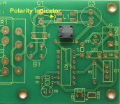
There is an error on the orientation of C7 on the PCB. The “+” is on the
wrong side.Our Jean-Paul and Subbu missed that single error and apologize for letting it pass undetected. (We say that's fine as long as everyone is aware of it") )
)
 [/url][/IMG]
L1 has no polarity but since it has pin numbers we used a footprint
symbol to solder it correctly. You can solder it the other way around
though.
C-4 is a a dual use pad that accepts SMD or through hole. Refer to thread postings for more information.
On the orientation of Q-2 - the dot on the cover should be at the thick line.
Suggested part placement sequence: WM8804, ES9023, MIC regs, resistor array and then the 100 nF and 20 pF caps …..
Work ESD safe ! The chips are ESD sensitive devices. If you have no ESD strap make sure you discharge yourself by touching a PE connected device with both hands.
In Europe that will be for instance the heating radiator or the metal workbench in your kitchen (check local regulations on that). Anything that has a good connection to earth ground will do.
Don't wear any clothing with fabric that builds up static electricity. Wearing polyester containing clothing while wearing sneakers (isolation from ground while building up static electricity!) will present the possibility that chips will be damaged when the static electricity finds a path to discharge to.
**Try to not overheat parts.**
Solder everything without L3,4,5,6 in place. Check the board for solder blobs and shorts.
After all voltages after the regulators are confirmed, also place and solder the inductors.
Clean the PCB with isopropyl alcohol 99%, let it dry thoroughly - and then check carefully (again)for solder blobs and/or shorts.
Close your eyes, keep your fingers crossed and switch it on.
Confirm correct voltages again at L3,4,5 and 6.
 [/url][/IMG]
When those voltages are confirmed still correct, then measure output DC voltage which should be only a few mV DC offset.
Now connect an SPDIF source (cdplayer, mediaplayer etc.). Also connect L + R outputs to your amp.
Open volume very slightly and press the play button on your SPDIF device. Slowly turn volume up and listen carefully if you hear non distorted audio.
Take a deep breath and open volume a little more. When you hear good sound please relax and experience the feeling of a winner.
Give the DAC a few hours to break in. You will notice sound quality improves over time.
There is a public Google doc (with pinouts) that can be helpful in reading and understanding important voltages along the circuit.
Subbu/JP DAC read sheet.
This composite has the correct information and should be used for proper orientation of Q2. Please see post #575 for more detail.

For builders who prefer screw terminals, the following are suggested as a quality option to the crimped style. See post #643 for details
2 pin Mouser
571-282834-2
4 pin Mouser
571-282834-4
2 pin Digi-Key
A98333-ND
4 pin Digi-Key
A98335-ND
*****
korbin69 has contributed these images (Post #911) that should be considered a standard for DAC board construction and correct voltages. Printing the photo and the read sheet from the Google docs can serve well as trouble shooting aids. The top-side photo shows how a properly stuffed and soldered build should appear. Please note the minimal amounts of solder requited.
Thanks Phil - a major assist highly appreciated by all.
This is a revised version of the initial posting on this thread. I contains a collection of general information, recommendations and methods leading to a successful base/stock build. Changes, clarifications and additions may occur over time. As with most projects, it is recommended members read through the entire thread before starting the project. Please PM me or post any significant information that would be helpful as project start-up items. Some photos/illustrations will be added for further clarification.
Suggested equipment:
0.7 mm or smaller 60/40 good quality tin/lead solder.
A small chisel tip around 2 mm on a good quality soldering iron.
Liquid, tacky or soft paste flux (ChipQuick recommended).
De-soldering braid.
Lighted magnifying lens/lamp for assembly and inspection. Example – Goose Neck Lamp
Small point tweezer, preferaby a type to which solder does not stick !
Suggested techniques:
Open SMD containers over the PCB and away from the edge of the work area.
Double check orientation/polarity (where it applies) before applying heat.
Tinning just one pad prior to attaching components appears best for adding minimal solder.
Solder just one tab/pin and confirm alignment on components with multiple leads.
With components that have multiple pins/leads please solder the diagonal pin secondly. Now you know for sure that the chip is aligned correctly and can't change it's position anymore.
Some helpful videos on surface mount soldering -
Professional techniques
diyAudio Project example
There is an error on the orientation of C7 on the PCB. The “+” is on the
wrong side.Our Jean-Paul and Subbu missed that single error and apologize for letting it pass undetected. (We say that's fine as long as everyone is aware of it
)
L1 has no polarity but since it has pin numbers we used a footprint
symbol to solder it correctly. You can solder it the other way around
though.
C-4 is a a dual use pad that accepts SMD or through hole. Refer to thread postings for more information.
On the orientation of Q-2 - the dot on the cover should be at the thick line.
Suggested part placement sequence: WM8804, ES9023, MIC regs, resistor array and then the 100 nF and 20 pF caps …..
Work ESD safe ! The chips are ESD sensitive devices. If you have no ESD strap make sure you discharge yourself by touching a PE connected device with both hands.
In Europe that will be for instance the heating radiator or the metal workbench in your kitchen (check local regulations on that). Anything that has a good connection to earth ground will do.
Don't wear any clothing with fabric that builds up static electricity. Wearing polyester containing clothing while wearing sneakers (isolation from ground while building up static electricity!) will present the possibility that chips will be damaged when the static electricity finds a path to discharge to.
**Try to not overheat parts.**
Solder everything without L3,4,5,6 in place. Check the board for solder blobs and shorts.
After all voltages after the regulators are confirmed, also place and solder the inductors.
Clean the PCB with isopropyl alcohol 99%, let it dry thoroughly - and then check carefully (again)for solder blobs and/or shorts.
Close your eyes, keep your fingers crossed and switch it on.
Confirm correct voltages again at L3,4,5 and 6.
When those voltages are confirmed still correct, then measure output DC voltage which should be only a few mV DC offset.
Now connect an SPDIF source (cdplayer, mediaplayer etc.). Also connect L + R outputs to your amp.
Open volume very slightly and press the play button on your SPDIF device. Slowly turn volume up and listen carefully if you hear non distorted audio.
Take a deep breath and open volume a little more. When you hear good sound please relax and experience the feeling of a winner.
Give the DAC a few hours to break in. You will notice sound quality improves over time.
There is a public Google doc (with pinouts) that can be helpful in reading and understanding important voltages along the circuit.
Subbu/JP DAC read sheet.
This composite has the correct information and should be used for proper orientation of Q2. Please see post #575 for more detail.
For builders who prefer screw terminals, the following are suggested as a quality option to the crimped style. See post #643 for details
2 pin Mouser
571-282834-2
4 pin Mouser
571-282834-4
2 pin Digi-Key
A98333-ND
4 pin Digi-Key
A98335-ND
*****
korbin69 has contributed these images (Post #911) that should be considered a standard for DAC board construction and correct voltages. Printing the photo and the read sheet from the Google docs can serve well as trouble shooting aids. The top-side photo shows how a properly stuffed and soldered build should appear. Please note the minimal amounts of solder requited.
Thanks Phil - a major assist highly appreciated by all.
Last edited:
Chip-Quick has been the best for me. It is in a syringe that us very useful. It's primary use is for parts removal, but just using the flux is great. I always clean with alcohol and Dow Bathroom cleaner - then a shop vac.
Chipquick Video
CQ Product Line
Chipquick Video
CQ Product Line
Better use a 5 mm film cap for C4 as in BOM. BTW you use too much solder.
- Q2 should be the other way around !
- L1 has no polarity but since it has pin numbers they used a footprint symbol to solder it correctly. You can solder it the other way around though.
- First WM8804 and then the 100 nF caps would be my choice but the caps are already soldered ...
You are right that a dedicated build thread would be better, here it is:
http://www.diyaudio.com/forums/digital-line-level/245233-build-thread-building-subbu-dac-v3-se.html
I asked the mods to transfer posts 830 and onward to the new thread.
Last edited:
A new thread for the fearless builders of Subbu DAC V3 SE (SPDIF version). Please share information and possible troubles you might encounter. You may also want to report your findings regarding modifications or just to tell your results when your DAC is ready and playing.
Last edited:
"Better use a 5 mm film cap for C4 as in BOM. BTW you use too much solder.
- Q2 should be the other way around !
- L1 has no polarity but since it has pin numbers they used a footprint symbol to solder it correctly. You can solder it the other way around though.
- First WM8804 and then the 100 nF caps would be my choice but the caps are already soldered ..."
I've been fighting excess solder all morning. I'm trying to carry a small amount just on the tip but I haven't found the right size/shape yet. I'll be glad to hear your recommendations. I'm using a 1mm solder because that's all I have today - that may be the problem. It may be well worth it to wait and order something thinner.
I bought all the "Alt" parts so I can change C4 if that's the recommendation.
I don't see any markings on L1 and it looks symmetrical to me.
I thought you said soldering the major SMDs last would cause less stress on the PCB pads???
Last edited:
If 1 mm solder is too thick. 0.7 mm or thinner would be better. You can remove excess solder with desoldering braid. But you will heat up stuff again so better use the right solder from the beginning and no excess solder will be there.
Don't know about stress of the components !? What I do know is that soldering gold plated PCBs can be difficult. Still we thought it would nice to have the last version gold plated.
Don't know about stress of the components !? What I do know is that soldering gold plated PCBs can be difficult. Still we thought it would nice to have the last version gold plated.
Just checked - RS still has some Silver Bearing Solder that I remember being very thin. I'll run over there this afternoon. I think the quality is relatively high.
Hi I have used silver bearing solder and still have such in stock. It is mechanically stronger than normal 60/40 tin lead solder. However I think it does not make much difference in sound quality (although I tricked myself long ago in believing that). I would like to advise to use good 60/40 solder that flows nicely like Alpha Metals Fluitin. The copper containing (Sn60/Pb38/Cu2) version is very good quality. I think it is called Fluitin 1535.
There are few solders that flow very good and that apparently rare quality is just what we need on a gold plated PCB !
There are few solders that flow very good and that apparently rare quality is just what we need on a gold plated PCB !
Last edited:
88.6%Sn/1.8%Cu/9.5%Ag/0.1%Au - is what my 1mm solder is (from Partsconexxion). I bought one of those 1000 resistor/1000 capacitor packages on ebay a few years ago. Think I should just take the time to practice with some of those, and file one of my tips to something that works. I'll report back. I had it down pretty good on the MR-FE amps.
Last edited:
Filing off metal plated solder tips is a recipe for disaster. Just obtain a smaller tip. The iron coating of a tip has a function. You are not using a transformer type soldering gun with plain copper tip are you ?
BTW you use the lead free solder variant that we warned for several times. This DAC is best soldered with plain old lead containing solder like the Sn60/Pb40 standard solder everybody used in a time when only one solder existed for electronics: 60/40
You will never get nice looking and reliable joints with the solder you use now.
Last edited:

It's probably just me. From other threads where the topic came up most folks recommended the addition of either silver and/or gold as an enhancement to the flow and stability for audio use. It admittedly approaches an "Angles on the head of a pin" type discussion at times, but I have been following that advice on several thru-hole projects.
No desire on my part to dispute what's best on this project as you are it's designer - and particularly with the high SMD parts count. I'll be more than happy to take your lead - even if that means holding off a few days to get the right stuff.
No desire on my part to dispute what's best on this project as you are it's designer - and particularly with the high SMD parts count. I'll be more than happy to take your lead - even if that means holding off a few days to get the right stuff.
Last edited:
Aha, I get it. Feel free to use audiophile solder if you like. I doubt it makes much difference with SMD parts as they often make direct contact with PCB tracks when manually soldered. Hey I just want anyone building the V3 to have it look good and perform good if not excellent AND being reliable. While you use audiophile lead free solder I doubt the quality of the "cold joints" I saw on the pics. My guess is that 60/40 would have made better joints but we've entered religious grounds with many guys sharpening their knives now.
That we designed this DAC says nothing about our competence in soldering or what's best !
Secret message : ! egabrag si redlos eerf deal
That we designed this DAC says nothing about our competence in soldering or what's best !
Secret message : ! egabrag si redlos eerf deal
Last edited:
Man!! You got to give me a hint -at least what that language is.
Google Translate doesn't even get me close: "egabrag si redlos eerf deal"
Google Translate doesn't even get me close: "egabrag si redlos eerf deal"
I use this ancient encrypted language since I learnt the NSA/GCHQ checks our stuff in Europe. Till now they haven't broken the code ! It was a tip from Snowden. He said the tricky part is when there are wives/girl friends with mirrors around.
Wait a moment, maybe I know now why my PCBs are held at the german customs. Spooky stuff.
Wait a moment, maybe I know now why my PCBs are held at the german customs. Spooky stuff.
Last edited:
- Home
- Source & Line
- Digital Line Level
- Build thread - building the Subbu DAC V3 SE