Probably not a problem but you may have installed the LED backwards. Can you measure the voltage across the LED? When operating normally the voltage should be around 1.7v. If it's in backwards then it won't conduct and you'll see the full 5v across the LED and no light. If that's the case you just need to unsolder it and install it the right way.
---Gary
I'm getting 1.97v across the led. Any ideas? Is the function basically as on/off indicator? Thanks, Gary.
I'm getting 1.97v across the led. Any ideas? Is the function basically as on/off indicator? Thanks, Gary.
Yes, the only function of the LED is as an on/off light. The power supply works just fine without it. Since your power supply works fine, I'd be tempted to just leave it alone and not worry about it. You could try replacing the LED and double checking the orientation before putting it in. But probably more trouble than it's worth.
---Gary
Replace the LED just in case and check the cathode for the correct placement. Check the resistor too. It should be 1k4 for a non-ultra bright shining green LED. If you feel it is too bright even with 1k4 you could use 1k8 or 2k. With 2 kOhm the LED will have 1.6 mA flowing through it which must result in a dimmed shining green LED when using standard 3 mm LEDs. For other colors values might have to be adapted as they have a different Uf. People that use bright blue LEDs don't need to apply for info as they are dismissed ")
Calculation: 5V -1.8V = 3.2 V. 3.2V/Rled= Iled. So 3.2/2000= 0.0016 A = 1.6 mA
If you use the Molex KK connector for the LED you can solder thin wire to the LED at the other side of the wires, insulate the LEDs lead wires with thin heat shrink tubes and heat those with a lighter to shrink them. Now put some adhesive (sticker) on the front panel (to avoid scratches from drilling), determine the place where you want the LED, then drill a 3 mm hole in the front panel of the case with a sharp 3 mm drill, remove the adhesive and the debri and use a 10 mm drill to deburr the hole Do this by hand, just turn the drlll lightly clockwise and feel if the burrs are gone. Don't overdo. Now put the LED in the hole from the backside. Secure it with some 2 component glue at the back side of the front panel. It is nicer to use a so called LED clip for the LED or a prefabricated LED with clip for this purpose. Check the distributors for finished products. For a few $ or Euro the results will be better. I use these made by Dialight and I think they're OK:
http://nl.farnell.com/dialight/558-0201-007f/led-indicator-he-grn/dp/1519439
This way the LED has a real purpose. I thought this was understood as it is no rocket science but many use the LED simply on the PCB which seems ineffective to me when the case is closed
Last edited:
When using a LED clip the hole must be 4 mm in most cases but check first. Also deburr the hole with a 10 mm drill by hand after drilling the 4 mm hole. With a LED clip you camouflage the clearly visible drilling.
I hope it is clear that using the Molex connectors will result in easy disassembly of the case when the device will be modded, repaired (Subbu DACs don't break down but still...) etc. This counts for both the DAC board and the PSU board. You will end up with an unusable DAC when you will have to desolder wires a few times from the PCB.
OK class dismissed
Last edited:
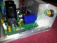
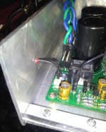
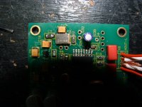
Here is an example of the technique JP describes. It's on a FE power amp but is the same thing. I didn't finalize with glue/RTV as the chassis serves as home for a couple versions of the amp. I used tiny copper tube from the local craft/hobby store on the LED leads to replace the female Molex and avoid soldering to the pins.
Attachments
Last edited:
Ah Bob, always in the first rows of the class Thanks for the pictures.
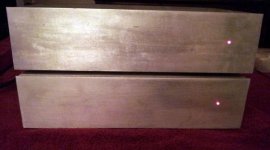
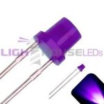
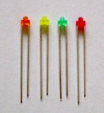
When a high speed drill is used (so no deburring necessary of the hole) and flat round 3 mm LEDs are chosen it really looks good as they will be flush with the surface of the front panel. Of course that won't happen with the Dialight ready made panel LEDs. There are several lengths of these flat head LEDs so check and choose according the thickness of your front panel. BTW when I googled for a picture of the flat round LEDs I just discovered that these also exist in a kinky purple version. As any color is better than blue I suppose it won't harm to show the picture.
Of course I found even nicer 1.8 mm LEDs. They will not be flush to the surface but they will be recessed as with Apple Macs. Wish I had discovered those earlier as it seems they will give a "chique" look to DIY gear. And then I suddenly thought: how many pages can we fill talking about Subbu DAC's power LED ?
Thanks for the pictures.When a high speed drill is used (so no deburring necessary of the hole) and flat round 3 mm LEDs are chosen it really looks good as they will be flush with the surface of the front panel. Of course that won't happen with the Dialight ready made panel LEDs. There are several lengths of these flat head LEDs so check and choose according the thickness of your front panel. BTW when I googled for a picture of the flat round LEDs I just discovered that these also exist in a kinky purple version. As any color is better than blue I suppose it won't harm to show the picture.
Of course I found even nicer 1.8 mm LEDs. They will not be flush to the surface but they will be recessed as with Apple Macs. Wish I had discovered those earlier as it seems they will give a "chique" look to DIY gear. And then I suddenly thought: how many pages can we fill talking about Subbu DAC's power LED ?
Attachments
Last edited:
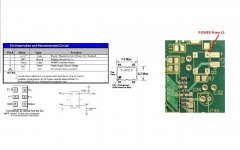
There is a problem here. The second picture in post #1 shows the dot in the correct orientation. It is reversed in the next one.
In post #6 JP states that Q2 needs to be reversed but no reference to which photo, so there could be some confusion. I need to straighten that out so I made a composite keying on the power supply for Q2.
That means the "Dot at the thick line" indication in post #1 is also incorrect, adding more confusion.
Before I make corrections to the first post - please confirm.
Attachments
Last edited:
No problem Bob as we're still breathing. The picture you just posted is right so for you guys it is post #575 that is right. I am flabbergasted in what ways I can make clear how to solder Q2 Many 2.6 DACs have been soldered and no one asked....
Something like this ? "The text written on Q2 should be aligned with the text C17 on the PCB" ?!?! You decide as it is your language. I can make it perfectly clear in german/dutch language if needed. After some thinking a small yellow dot on the PCB indicating pin 1 would have made it better but you all really should be able to read datasheets and follow PCB tracks when you want to build a device like this. No excuse but this is a DIY thing not a kit or ready made device. Any builder should take the challenge to build this thing with ....OMG... some own thinking
IMO no human eye can see that but you are on the right track by asking first. The photo normally helps a lot so no reservations about that please.
Many 2.6 DACs have been soldered and no one asked....Something like this ? "The text written on Q2 should be aligned with the text C17 on the PCB" ?!?! You decide as it is your language. I can make it perfectly clear in german/dutch language if needed. After some thinking a small yellow dot on the PCB indicating pin 1 would have made it better but you all really should be able to read datasheets and follow PCB tracks when you want to build a device like this. No excuse but this is a DIY thing not a kit or ready made device. Any builder should take the challenge to build this thing with ....OMG... some own thinking
Its not soldered on yet! look a bit closer instead of picking up things that are not finished
That's one reason I do not like asking questions with a photo and Thank you Sidney
IMO no human eye can see that but you are on the right track by asking first. The photo normally helps a lot so no reservations about that please.
Last edited:
..... a small yellow dot on the PCB indicating pin 1 would have made it better but you really should be able to read datasheets and follow PCB tracks......
That's exactly what I had to do to understand my mistake. Do I get any creds at all for " Better late than never"?


Just thinking: what would happen if all the builders would show up in a pub just to meet and discuss this DAC with some beer ? Hours of talk about the power LED ? C17 ? Connectors ? GaryB on polymer caps ? Subbu about still tasting the glue of the envelopes he used to sent the boards in ? Frustrated guys that did not get to the finish as they soldered Q2 wrong because I did not indicate that on the board ? Then hay forks, torches and a posse going after us
Let's not do that.
Let's not do that.
Last edited:

- Home
- Source & Line
- Digital Line Level
- Build thread - building the Subbu DAC V3 SE