a new modification thread
I just opened up a new thread to discuss modifications of the Subbu V3 DAC. After discussion with JP, it was agreed that it's better to keep this thread focused on helping people with the BOM build of the V3 DAC. I want to assure everyone that the BOM results in a very good sounding DAC, especially the version with the SAL-RPM capacitors.
We can discuss changes from the BOM in the new thread here http://www.diyaudio.com/forums/digital-line-level/246003-modifying-subbu-v3-dac.html
Thanks,
---Gary
This is a great idea Gary, and many thanks for the reassurance regarding the stock DAC's performance.
I have 2 PCB's on order, so I will build one as per BOM and the other I can use for experiment and comparison using the new thread for guidance.
Cheers - Ken
Thx atupi...I'll start on the dac pcb and see if there is anything else I need to order but as long as the p/n are correct I should have everything else. it just dawned on me....do we need to order an rca/coax connector for input? is there anything different compared to regular rca input/outputs?
Can somebody explain the footnote of Q1? "** - Check the E/B/C depending on the transistor package you use as SOT-32 and TO-126 have different pin arrangement"
Can somebody explain the footnote of Q1? "** - Check the E/B/C depending on the transistor package you use as SOT-32 and TO-126 have different pin arrangement"
....do we need to order an rca/coax connector for input? is there anything different compared to regular rca input/outputs?
Can somebody explain the footnote of Q1? "** - Check the E/B/C depending on the transistor package you use as SOT-32 and TO-126 have different pin arrangement"
You do need to get the SPDIF signal to the DAC. You could wire a cable directly to the board but that's not very convenient. Normally you'll add a connector. Even though RCA jacks are commonly used for SPDIF, I prefer to use BNC. The SPDIF signal chain is spec'd to be 75 ohm impedance and I've found that there is benefit in using 75 ohm coax for my digital interconnects and using BNC jacks and plugs spec'd for 75 ohms. But you only get the full benefit if you're willing to change the connectors on both sides - i.e. on both the DAC and the transport. If you want to go down this path, the Amphenol 112432 jack is a nice 75 ohm BNC connector that's available for a reasonable price at both Mouser and Digikey.
The footnote about EBC just says that the pin out of Q1 (BD140) is a function of the package so please check the datasheet and make sure you install it correctly.
---Gary
Here's a link to my attempt to have several inputs available. Different DAC but I use the BNC 90% of the time.
DAC Multi-Input.
DAC Multi-Input.
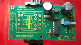
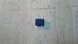
Started soldering my PSU pcb and noticed that the B1 part number from Mouser is not correct - p/n 512-DF01S. I believe it should be p/n 625-2W01G-E4. Can somebody confirm this and is there an updated BOM?
I've ordered this bridge:
Mouser Part #:
625-2W04G-E4
Manufacturer Part #:
2W04G-E4/51
but anything similar will do, so no reason to order from Mouser.
Happy soldering,
Adrian
I've ordered this bridge:
Mouser Part #:
625-2W04G-E4
Manufacturer Part #:
2W04G-E4/51
but anything similar will do, so no reason to order from Mouser.
Happy soldering,
Adrian
Atupi, I picked up NTE5305 at local store here.
Thx for the info and pics GaryB & bcmbob.. Hope to fire up the power supply by itself tonight.
btw I was really concerned about the small legs on the wmm804 and ess903 but I figured it out :
1. put liquid flux on the pads
2. wipe any excess off
3. place part on and align legs to pad
4. put solder on iron tip
5. put tip on one leg
6. apply liquid flux again on all legs
7. put solder on iron tip (little amount goes a long way) and place on legs
8. if you have any bridges just use wick.
9. check your work with a loupe or at least 4x magnification ... dependant on your vision I guess
Hope this helps.
Thank you for the heads up, I can ditch the DigiKey cart nowU2, U3, U5 and U4 are available from Mouser. They're listed as "New Product". Catalog #'s are 998-MIC5205-3.3YM5TR and 998-MIC5205-3.6YM5T. Yay for those of us who prefer Mouser
")
Hi, I do use polymer 100/10 myself for C2, C3 and C18. No problems, also with C5, C7 and C19 in 4.7 µF tantalum. The ones I got fit exactly (3.5 mm pitch) and the SEPC 100/16 are smaller with a smaller pitch (2.5 mm). They don't fit if you like shortest connection and a tidy built neat looking DAC. The 100/16 SEPC fit on the footprint for C22. I have the SEPC 100/16 but I don't use them on the V3.
With the V2.6 I once had oscillating MIC regs with ceramic caps at their outputs. in the hope that others read this: don't use ceramic caps straight after the regs !
thanks for pointing out that those caps have the wrong lead spacing. i do like tidy builds and have run some unrelated tests recently with a scope and seen first hand how just a few mm of additional capacitor lead length can affect their response to fast transients. this said, i've settled on a nichicon part (100uF/10v, 3.5mm, 7mOhm@100kHz, RR71A101MDN1 / 493-3711-ND).
-matt
Any suggestions on how to test Q2 is soldered correctly? Its really tough getting solder under each corner.
I agree, the worst part of the lot I think. My method was to LIGHTLY tin the pads on the PCB and also Q2's pads. Then flux the PCB pads, position Q2 and hold down with tweezers and hit the tiny metal pieces on Q2 with the iron. Hold for a couple of seconds and it should take.
To test I used the meter (on Ohms) with SMD probes to probe Q2's pins as high as possible - Follow schematic. Note pin 1 is not connected.
Cheers - Ken
Just started my own. First steps: solder the transformer to the power supply board, solder the ES9023 chip to the DAC board. Next step: wait for the component GB packet to arrive... Well, my building queue is nothing but empty, so I'll live with it.
It was nice to notice that the DAC chip had some space around it for hand soldering. And that solder seems to flow very nicely on that gold plated board.
It was nice to notice that the DAC chip had some space around it for hand soldering. And that solder seems to flow very nicely on that gold plated board.
cheers everyone! a quick advice is needed for parts to be substituted.
dac module
L3-L6 - does it have 600ohm resistance?
PS
same with L1? What could be the alternative? placing 3x 100 ohm chokes in series?!
It turned out to be quite difficult to find these parts if not placing order on Mouser...
dac module
L3-L6 - does it have 600ohm resistance?
PS
same with L1? What could be the alternative? placing 3x 100 ohm chokes in series?!
It turned out to be quite difficult to find these parts if not placing order on Mouser...
- Home
- Source & Line
- Digital Line Level
- Build thread - building the Subbu DAC V3 SE