
beads for L1, L2
Jean-Paul/Phil,
The recommended inductors for L1-2 are now obsolete. Is this ok:
ELJ-FB470KF Panasonic | Mouser
Regards,
Freeman
Jean-Paul/Phil,
The recommended inductors for L1-2 are now obsolete. Is this ok:
ELJ-FB470KF Panasonic | Mouser
Regards,
Freeman
Jean-Paul/Phil,
The recommended inductors for L1-2 are now obsolete. Is this ok:
ELJ-FB470KF Panasonic | Mouser
Regards,
Freeman
Hi Freeman,
Those have closest specs, 100uH, same 1812 footprint, and are available :
PM1812-101J-RC J.W. Miller | Mouser
Regards,
Phil
Jean-Paul/Phil,
Would you have an extra dac board and chip to sell?
Thanks.
Regards,
Freeman
Hi Freeman
Drop me a mail to my personal boxmail.
Regards,
Phil
Silver or Chrome would be my choice ")
Best regards,
Best regards,
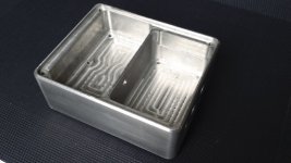
Next step anodizing.
Gold,gray or black can't make up my mind.
Beautifull box ! Wow ! Any cheap GB planned ? Aluminium is light
In your shoes I will put a connector at each side of the partition wall instead a hole to allow even more EMC isolation ? two tunnels for AC wires with a widther box if JG buffer used (need to be feeded by a separate supply) : to allow an AC plug at the bottom of the box but separated by a partition wall from the DAC board aera !
Will make the box a little bigger despite the big thick of the partition wall to move away more the PS unit from the pcb dac unit ? For a second PS (JG buffer) : PS compartiment splitted in two to isolate the traffos from each other ?).
And we will ask to adapt the new PS of Jean-Paul for a symetric +/- 15 V for the Joachim Gerrard buffer ! Nah, it will be only + 5V
In your shoes I will put a connector at each side of the partition wall instead a hole to allow even more EMC isolation ? two tunnels for AC wires with a widther box if JG buffer used (need to be feeded by a separate supply) : to allow an AC plug at the bottom of the box but separated by a partition wall from the DAC board aera !
Will make the box a little bigger despite the big thick of the partition wall to move away more the PS unit from the pcb dac unit ? For a second PS (JG buffer) : PS compartiment splitted in two to isolate the traffos from each other ?).
And we will ask
to adapt the new PS of Jean-Paul for a symetric +/- 15 V for the Joachim Gerrard buffer ! Nah, it will be only + 5V
Last edited:
First solder regs. Connect the DAC to the PSU and switch it on. Measure the 4 regs. When OK switch it off and then solder the WM8804 and ES9023.
Thank you for the reply, but
WM8804, ES9023 and resistors are already soldered to the board.
I think I have to go to the first test without inductors suggested in 1st post of this thread.
Northernsky
And you can see Gary posted on the first page a link to Korben69 aka Phil voltages measurements picture on all the pins !
So it's easy to find if you reg(s) is broken, shorted, etc ! Look at the picture !
If one of the chip has a bad voltage measurement but the regs show an acurate voltage, you have to carefully resolder the chips pins with a magnifying glass and some flux ! Most of the time it is the Wolfson's chip which has a bad contact !
Most of the time it is the Wolfson's chip which has a bad contact !
This my second SMD project. The Wire headphone amp went straight, but Subbu ICs... what a headache!
northernsky
Hi,
started soldering Subbu DAC. When I soldered U3 mic I got the impression of a flash
while soldering the three side feet. Do you think I damaged the mic?
northernsky
Hi,
finally I completed DAC soldering and made the preliminary test, measuring VDC at L3-L6 without these inductors soldered.
I think the test is OK, but please give a confirmation, since I am not expert.
On one side of inductors I measured the expected VDC and on the other side I got obviously 0VDC as in the rest of the circuit. But only for L5 I get the measurement as in the picture in post #1 describing the test; for the others I get 3.2 or 3.6VDC on the reversed pin. But I assume is an error in the picture,
am I right?
Thank you
Northernsky
Hi Northernsky
Please post pics of your board.
Use MSPaint to add measured voltages and report here
It will be very usefull to see your progresses.
Regards,
Phil
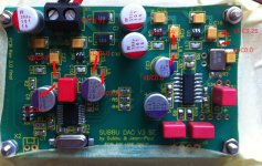
Thank you Phil for your support. This is the picture of my pcb with measured VDC
northernsky
Attachments
You're welcome Northernsky
Please refer to Post #911 in this thread.
You'll find some usefull measures.
As you haven't populated L3/4/5/6, you can't measure further
BTW, 50MHz XO isn't fed, same comment for C17/22/13/8.
So, please check again your voltages on Tantalum C27/26/15/16.
Please confirm you've measured positive side of the caps (+).
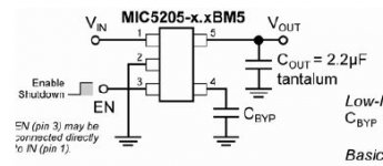
If previous request is correct, then I suspect U3 (MIC5205 3.3V) to be faulty.
Check U3 pins 4 (Gnd) & 5 (Vout) values, according to attached pic.
Regards,
Phil
Please refer to Post #911 in this thread.
You'll find some usefull measures.
As you haven't populated L3/4/5/6, you can't measure further
BTW, 50MHz XO isn't fed, same comment for C17/22/13/8.
So, please check again your voltages on Tantalum C27/26/15/16.
Please confirm you've measured positive side of the caps (+).
If previous request is correct, then I suspect U3 (MIC5205 3.3V) to be faulty.
Check U3 pins 4 (Gnd) & 5 (Vout) values, according to attached pic.
Regards,
Phil
Attachments
Last edited:
- Home
- Source & Line
- Digital Line Level
- Build thread - building the Subbu DAC V3 SE