I am using this power supply(post 896)-I supposed you are using original Subbu PSU for dac. If not forget my message.
http://www.diyaudio.com/forums/digi...build-thread-building-subbu-dac-v3-se-90.html
I communicated with Gentleman who designed this PS and he advised me to short the chokes near 24V output with heat sink on regulator(I already put)and yes DAC worked.According to him current output was low due to chokes and shortening them will give more current to DAC. Ultimately main input voltage do not drop now.
Still I wonder how DAC worked when I did not add heat sink or chokes were in action very first time.

I would like to thank you all for giving me tips.
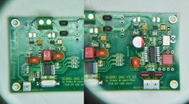
Despite having a perfectly working V3.0 DAC and a spare board I recently scored a built Subbu DAC in the Swap Meet section. It was advertized as lovingly built with perfect spec parts etc ...
but is not working due to a massive short somewhere.
I assumed that it was working and since the soldering looked quite good... but once connected to the psu the voltage of the power supply dropped to zero and the transistor heated up big time.
Luckily the psu survived.
Measuring I quickly discovered that I have full continuity across X1 so started to investigate down the way of power. Eventually I had all caps until the regs removed but still have continuity across X1 and all cap positions?? The caps (C16, C26, C15, C27) after the regs seem to be okay as well as the regs themselves (with DMM --> very high resistance).
Now with basically only blank pads staring at me I still have continuity... which leaves me puzzled. Please see the pics... any thoughts on that?
I hope it is just the described section... when anything further down is defective it goes in the bin (and so does my money).
PS. Pic composed from two shots through my magnifying lens.
but is not working due to a massive short somewhere.
I assumed that it was working and since the soldering looked quite good... but once connected to the psu the voltage of the power supply dropped to zero and the transistor heated up big time.
Luckily the psu survived.
Measuring I quickly discovered that I have full continuity across X1 so started to investigate down the way of power. Eventually I had all caps until the regs removed but still have continuity across X1 and all cap positions?? The caps (C16, C26, C15, C27) after the regs seem to be okay as well as the regs themselves (with DMM --> very high resistance).
Now with basically only blank pads staring at me I still have continuity... which leaves me puzzled. Please see the pics... any thoughts on that?
I hope it is just the described section... when anything further down is defective it goes in the bin (and so does my money
).PS. Pic composed from two shots through my magnifying lens.
Attachments
I finally got my DAC running. Problem was at WM. Removed and refitted WM and now DAC is working fine.
My special thanks to :
JP & Subbu for making this DAC.
Phil for doing the GB, helping me source the transformer and giving soldering tips.
Phil, Stixx, Eldam, baswamin, bcmbob, tuo, marce, GaryB & atupi for giving all the tips on the problems I faced.
This was my first DIY build ever. Never knew what SMD & Flux was. Always thought soldering is all about iron tip and solder wire. Someone would call me a foolish or too brave for taking this kind of a project first up. But after reading Subbu DAC reviews, I couldn't resist.
When I looked at the size of the parts when they arrived, I had almost given up. My friends Thecoolestone and Spiro gave me all the inspiration to complete this project. Without Thecoolestone, I would had never achieved this.
Finally DAC is running and I feel very happy about it. Not only it is an accomplishment but the building process has taught me some good DIY lessons.
Ready to move to Modifying V3 thread....
Thanks Again !!!
Darshan,
Can you also post 8804 readings when DAC is working?
From the voltage points bob has in the google doc, it looks like Pin 9, Pin 13, 14, 15 and 16 are different. It may point to something with Q1 but not sure why it would work for sometime only.
Thanks
Puzzled, I presume when playing it will play well until you turn it off?
@ darshanjoshi - Diode is the LED on the power supply. A couple more simple things to check: Turn off the DAC and disconnect the power supply. Check for a residual (stored) current on the PS (unplugged / switched off) and the DAC. A little bulb can be used to dissipate a charge if one exists. The pic shows one for larger power supplies but soldering some wires to a flashlight battery will work here. Just touch those wires to the power terminals on each board for a few seconds.
How to....
The 1, 5 and 20 sequence appears related to timing/sync as Gary and Marce describe, but clearing all the stored voltages might help pinpoint something.
I am new at this. I will check the video and report back my findings.
If there is issue with PS, I can check with one of my friends PS who has also build Subbu V3 and working fine.
Hi Darshanjoshi,
Your WM8804 values from pin 13 to 16 seems to be faulty to me.
Please check R4/R5/R6 values whose should be close to 0.029/3.52/3.52 according to your measures.
I suggest you to clean the right side/section of WM8804 using flux and desolder braid.
I suspect a short, but can't understand where and how do you pick a 3.52v value there....
Maybe I'm wrong and I'll complete my input with ES9023 soldered values soonly
Would you please check again and report ?
Regards
Phil
Despite having a perfectly working V3.0 DAC and a spare board I recently scored a built Subbu DAC in the Swap Meet section. It was advertized as lovingly built with perfect spec parts etc ...
but is not working due to a massive short somewhere.
I assumed that it was working and since the soldering looked quite good... but once connected to the psu the voltage of the power supply dropped to zero and the transistor heated up big time.
Luckily the psu survived.
Measuring I quickly discovered that I have full continuity across X1 so started to investigate down the way of power. Eventually I had all caps until the regs removed but still have continuity across X1 and all cap positions?? The caps (C16, C26, C15, C27) after the regs seem to be okay as well as the regs themselves (with DMM --> very high resistance).
Now with basically only blank pads staring at me I still have continuity... which leaves me puzzled. Please see the pics... any thoughts on that?
I hope it is just the described section... when anything further down is defective it goes in the bin (and so does my money
PS. Pic composed from two shots through my magnifying lens.
I would remove the beads and coils L1 and L2 and then test if you no continuity on X1 and if you have output voltage on the regs for the WM8804. If so then solder L1 and test again. Again OK then solder L2 etc.... Also checks the MIC regs with a magnifying glas and reflow if necessary. Soldering on the ES9023 is sloppy but I would reflow that one if you have dealt with the short.
BTW no warranty on this DAC ? It is embarassing that you have bought a non working item from a Diyaudio member. Such things shouldn't happen as there is a kind of basic trust between members IMO. At least that's the way I see it.
Last edited:
I finally got my DAC running. Problem was at WM. Removed and refitted WM and now DAC is working fine.
Congratulations !
This was my first DIY build ever. Never knew what SMD & Flux was. Always thought soldering is all about iron tip and solder wire. Someone would call me a foolish or too brave for taking this kind of a project first up. But after reading Subbu DAC reviews, I couldn't resist.
When I looked at the size of the parts when they arrived, I had almost given up. My friends Thecoolestone and Spiro gave me all the inspiration to complete this project. Without Thecoolestone, I would had never achieved this.
Finally DAC is running and I feel very happy about it. Not only it is an accomplishment but the building process has taught me some good DIY lessons.
An exceptional achievement. I know I can be quite harsh when non experienced DIYers build the V3 (certainly when the workmanship is poor or when unsafe things are done) but in this case I am happy that you took the challenge and you won ! Enjoy the DAC.
Last edited:
I see it quite the same way... especially since it was advertized with colourful words and all. Quite disappointed here but I guess I have to bite the bullet.BTW no warranty on this DAC ? It is embarassing that you have bought a non working item from a Diyaudio member. Such things shouldn't happen as there is a kind of basic trust between members IMO. At least that's the way I see it.
Thanks for your tips though
.No Marce, just one level of squeaking.Does your meter have a short squeak function (ie the squeak gets higher pitched/louder nearer the short)?
I checked ALL soldering joints with the magnifying glass and they look fine... even the ones on the ES9023 seem nicely flowed.Also checks the MIC regs with a magnifying glas and reflow if necessary
What troubles me is that I have continuity with 7 caps removed... I wonder where is the path of continuity? Also I can't power this thing up sans capacitors...
would it be safe to populate all new caps with those symptoms?
I checked ALL soldering joints with the magnifying glass and they look fine... even the ones on the ES9023 seem nicely flowed.
What troubles me is that I have continuity with 7 caps removed... I wonder where is the path of continuity? Also I can't power this thing up sans capacitors...
would it be safe to populate all new caps with those symptoms?
One of my friends had similar problem. Problem was MIC only.
Removing, cleaning the pads and resoldering helped him solve the problem.
I had a similar problem with the U6 reg. One leg was bridged and was just barely noticeable. I ended up removing L1 and L2 and the beads but still the problem persisted. Continuity was present.
Next I started with removing the U6 regs, cleaning the pads and then resoldering the reg with just the right amount of solder required solved the problem.
Next I started with removing the U6 regs, cleaning the pads and then resoldering the reg with just the right amount of solder required solved the problem.
Looking at the schematic I already investigated in this direction. But will check again. All MIC's are nicely soldered but maybe s'thing is hiding underneath...MIC's pin 3 tie to pin 1, pin 2 connect to ground, pin 1 or pin 3 short to pin 2 will have continuity at X1. Pin 5 and pin 4 on the other side and with wider space, unlikely will short to other side of pin 1,2 and 3.
Thanks all!
I finally got my DAC running. Problem was at WM. Removed and refitted WM and now DAC is working fine.
Hi Darshan, nice to read you've got it working fine
Congrats

Regards
Phil
Looking at the schematic I already investigated in this direction. But will check again. All MIC's are nicely soldered but maybe s'thing is hiding underneath...
Thanks all!
Hi Oliver
I fully agree with JP, syyma, darshan & Thecoolestone position.
Go investigate all MIC5205 regs soldering pads.
Soldering job is very good, using a thin amount of solder.
I'm wondering about solder used, it seems to be unleaded, is it ?
Do you have a pic from bottom side, and have you removed X1 ?
Regards
Phil
Congratulations !
An exceptional achievement. I know I can be quite harsh when non experienced DIYers build the V3 (certainly when the workmanship is poor or when unsafe things are done) but in this case I am happy that you took the challenge and you won ! Enjoy the DAC.
Thanks for the kind words. DAC sound is nice and clean.
Hi Darshan, nice to read you've got it working fine
Congrats
Regards
Phil
Thanks a lot !!
I fully agree with JP, syyma, darshan & Thecoolestone position.
Go investigate all MIC5205 regs soldering pads.
Soldering job is very good, using a thin amount of solder.
I'm wondering about solder used, it seems to be unleaded, is it ?
Do you have a pic from bottom side, and have you removed X1 ?
Checked all MIC's with a 8x magnifier and tested them with buzzer function. All have continuity which cannot be true. None of the parts are looking abused or burned. All tant caps 4.7uF before the regs buzzed (and were removed probably unnessecarily), all tant caps AFTER the regs are fine. To continue the story I removed U3 -> pads underneath clean and no bridges. The desoldered U3 on my desk has no continuity between pin 1 and 2... so no short here although it buzzed before. X1 is removed, no traces of solder. I am at a loss.
Attachments
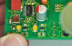
What if shorted at U4, U5 and U6? Power tee off at pin 1 of X1, power route to L1, L2 for U3 & U4 respectively. I see L1 still in the board but not sure about L2. If short somewhere at U4 continuity will present at X1, assumed L2 not remove from the board. Try remove L2 and re-check continuity at X1 since you already have U3 removed.
Sidney
Sidney
What I will do are:
1. Remove L1 and measure. If the continuity is gone, then you know the issue is from the down stream of L1. If situation doesn't change, then
2. Remove L2 and measure. If the continuity is gone, then the issue is from the down stream of L2. If nothing is changed, then you can focus on the circuitry on WM side.
This approach should help narrowing down what to check next.
Good luck!!
- Home
- Source & Line
- Digital Line Level
- Build thread - building the Subbu DAC V3 SE