Hi all,
I'm new to this forum but I've been lurking around in this forum from time to time. After spending countless hours on weeknights and weekends, I finally have a USB DAC (called the NV1) whose performance levels are satisfactory.
At the heart of the NV1 is a 32-bit microprocessor from Microchip's PIC32 family. The processor supports full speed USB 2.0, which allows up to 24-bit 96kHz audio to be streamed from the USB port without requiring any special drivers to be downloaded and installed.
Custom firmware was developed (this took the longest) to stream the digital audio data from the USB computer into its memory, and finally out to the actual DAC itself. The NV1 operates in asynchronous mode with feedback to ensure that the audio and USB clock domains are completely independent from each other. In fact, the audio clocks are driven by a dedicated ultra-low jitter oscillator while another oscillator provides the clock for the USB module.
Asynchronous mode works well as you guys may already know. It works almost too well, as you will see in the measurements below.
The PCB picture shows a missing component at one corner - that component is a rotary encoder with a switch to enable digital volume and mute control. These controls are processed in the MCU and sent to the USB host and actual DAC. The DAC performs the actual digital attenuation, which results in click/pop/hiss free volume control.
Without any further ado, here are some pictures of the board and audio performance results!
The prototype PCB - asynchronous USB in, RCA out
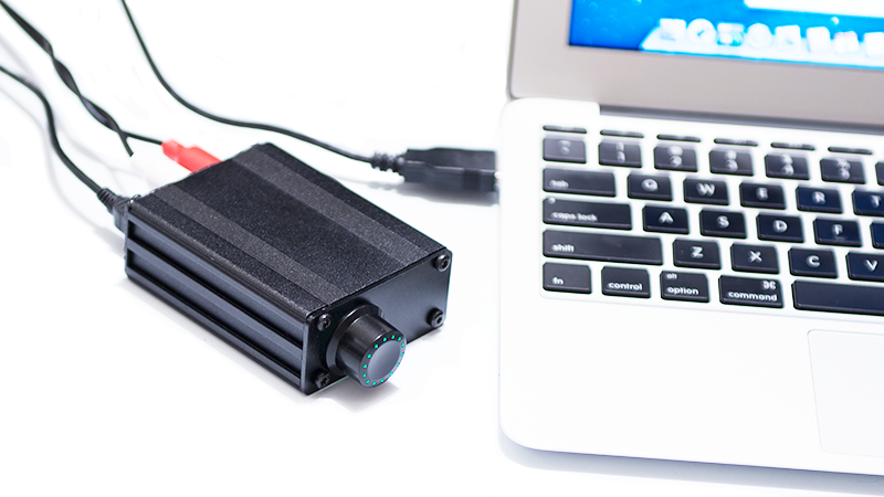
Housed in a prototype case, streaming music from my Macbook Air.
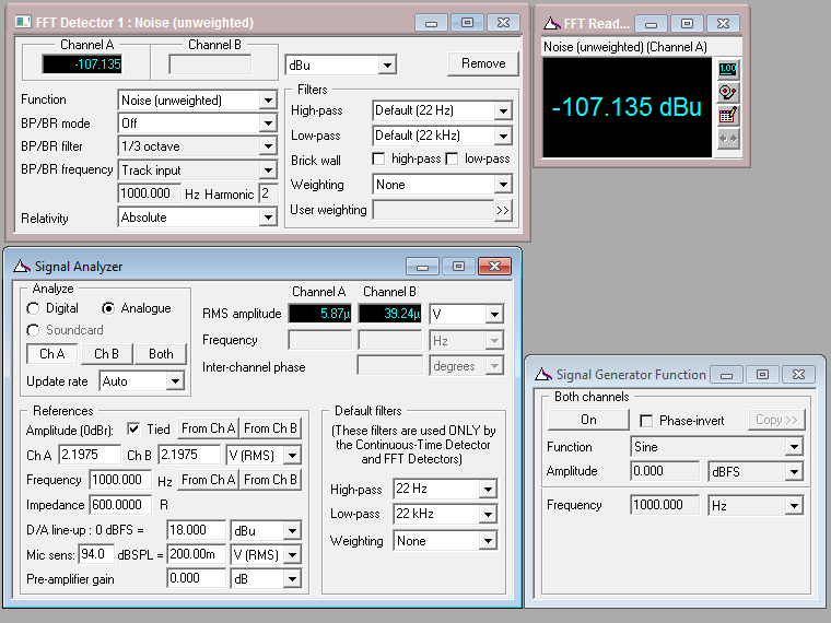
The FFT noise floor

-107 dBu noise floor unweighted (about -110 dBu for A-weighting)
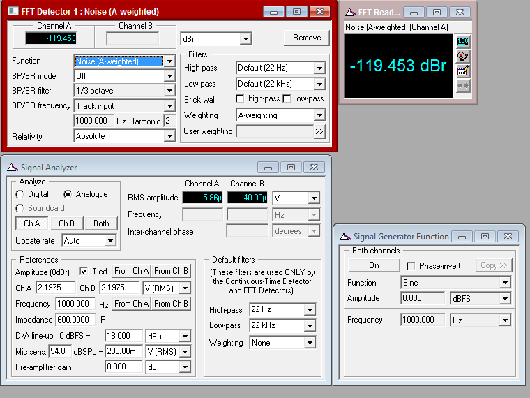
-119 dB signal to noise A-weighted
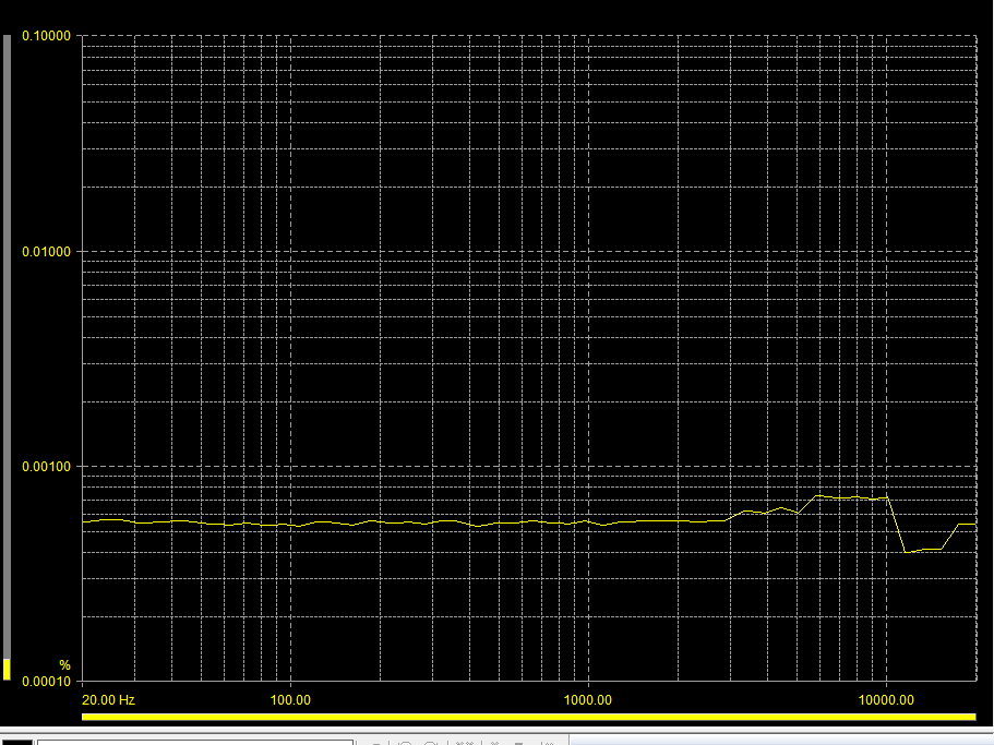
Various THD+N Measurements
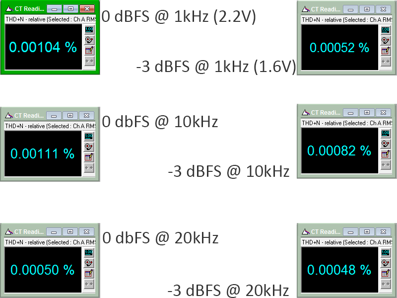
THD+N vs. freq @ -3 dBFS, about 0.0005% - 0.0008%
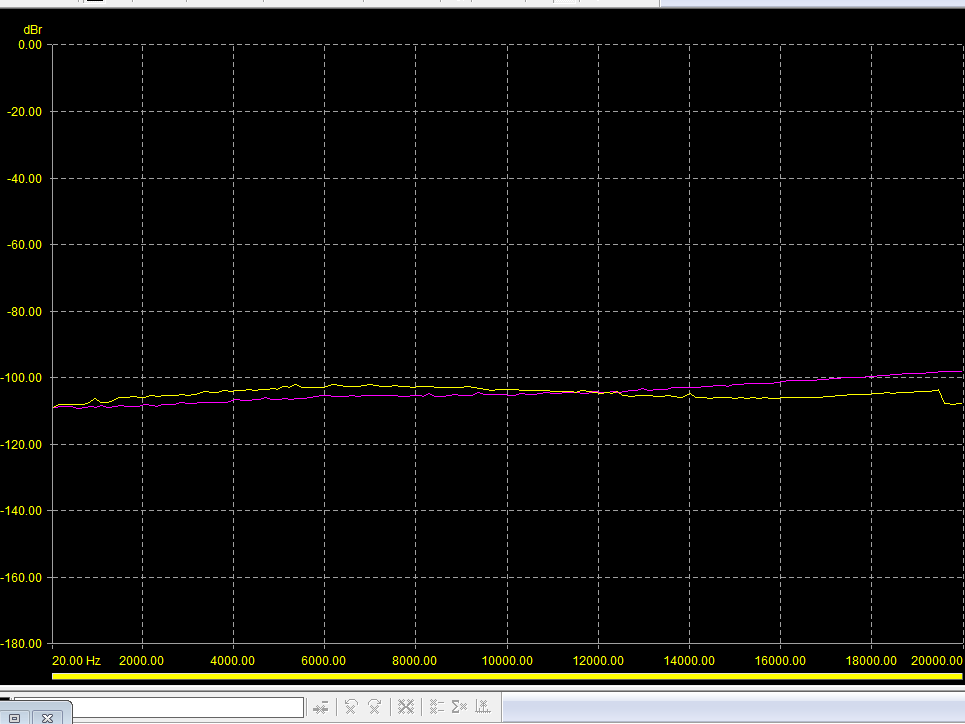
Crosstalk (looks like there are some minor layout issues that will be addressed for the next PCB revision)
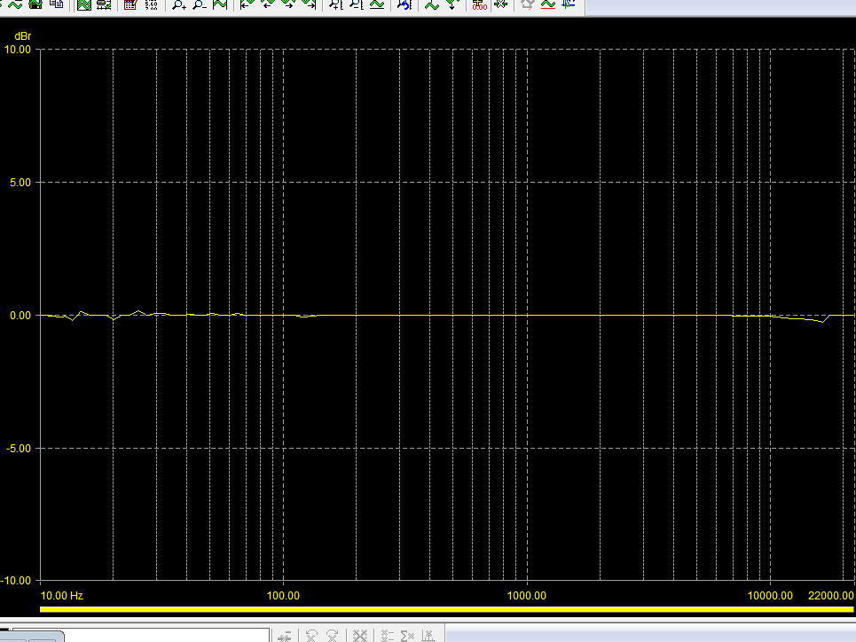
Frequency response
That's it for now.") I will have additional test results later. If you guys have any test requests, I'll be glad to perform them and post the results.
I will have additional test results later. If you guys have any test requests, I'll be glad to perform them and post the results.
I'm new to this forum but I've been lurking around in this forum from time to time. After spending countless hours on weeknights and weekends, I finally have a USB DAC (called the NV1) whose performance levels are satisfactory.
At the heart of the NV1 is a 32-bit microprocessor from Microchip's PIC32 family. The processor supports full speed USB 2.0, which allows up to 24-bit 96kHz audio to be streamed from the USB port without requiring any special drivers to be downloaded and installed.
Custom firmware was developed (this took the longest) to stream the digital audio data from the USB computer into its memory, and finally out to the actual DAC itself. The NV1 operates in asynchronous mode with feedback to ensure that the audio and USB clock domains are completely independent from each other. In fact, the audio clocks are driven by a dedicated ultra-low jitter oscillator while another oscillator provides the clock for the USB module.
Asynchronous mode works well as you guys may already know. It works almost too well, as you will see in the measurements below.
The PCB picture shows a missing component at one corner - that component is a rotary encoder with a switch to enable digital volume and mute control. These controls are processed in the MCU and sent to the USB host and actual DAC. The DAC performs the actual digital attenuation, which results in click/pop/hiss free volume control.
Without any further ado, here are some pictures of the board and audio performance results!
The prototype PCB - asynchronous USB in, RCA out
An externally hosted image should be here but it was not working when we last tested it.
Housed in a prototype case, streaming music from my Macbook Air.
The FFT noise floor
-107 dBu noise floor unweighted (about -110 dBu for A-weighting)
-119 dB signal to noise A-weighted
Various THD+N Measurements
THD+N vs. freq @ -3 dBFS, about 0.0005% - 0.0008%
Crosstalk (looks like there are some minor layout issues that will be addressed for the next PCB revision)
Frequency response
That's it for now.
I will have additional test results later. If you guys have any test requests, I'll be glad to perform them and post the results.Schematic would be great
Didiet
Some people are strange. They inform us about their great achievements
but what for? I might post a electrical drawing, I might make DIY kit =) Gee Christ, what a planet we are become
- Status
- This old topic is closed. If you want to reopen this topic, contact a moderator using the "Report Post" button.
- Home
- Source & Line
- Digital Line Level
- USB Audio on a PIC32 processor and a PCM1796