TDA1541
Hi Zsolt,
your idea about replaceable solution board on some pin IC header is nice.
I had a some time to run over evolution of DEM clocking on this community, including -ecdesigns- thread") , and somehow collected few of implementations of DEM clocks in here (see attachments).
, and somehow collected few of implementations of DEM clocks in here (see attachments).
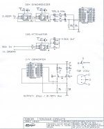
To make DEM externally clocked I would choose one of options:
1. BCK as in John's MK4;
2. clock of 350kHz or 705 kHz ("tdacir1" of John is far better than "newdem1" or "dem2" because of reclock signal attenuation and less jitter).
Why those two ways?
Because both are universal in our Fs range - from 44.1kHz to 384kHz, IMO.
However I want to notify, that last implementation (November 2012) of DEM clocking by John is free running low frequency DEM clock and here is a link, reasoning why: http://www.diyaudio.com/forums/digital-line-level/79452-building-ultimate-nos-dac-using-tda1541a-461.html#post3237361, post 4601.
Thanks
Saulius
One aspect regarding TDA1541 core board was not decided: synchronous DEM clocking
I'm not sure we should follow Setup's design as there are many different DEM clocking circuits floating around... from ones like Henk Ten Pierick’s to others using a simple inverter on BCK. Also this thread discusses TDA1541 DEM reclocking but I'm sure -ecdesigns- marathon thread has lot of information.
Which implementation should we use?
What about having free running DEM clock only on the core board and have synchronous DEM clocking on a daughter board - e.g. simply plugged into an 14pin IC header or similar - one could try different implementations like that. Nevertheless we should implement one of the synchronous DEM clocking solutions on this daughter board.
Thanks,
Zsolt
Hi Zsolt,
your idea about replaceable solution board on some pin IC header is nice.
I had a some time to run over evolution of DEM clocking on this community, including -ecdesigns- thread
, and somehow collected few of implementations of DEM clocks in here (see attachments). To make DEM externally clocked I would choose one of options:
1. BCK as in John's MK4;
2. clock of 350kHz or 705 kHz ("tdacir1" of John is far better than "newdem1" or "dem2" because of reclock signal attenuation and less jitter).
Why those two ways?
Because both are universal in our Fs range - from 44.1kHz to 384kHz, IMO.
However I want to notify
, that last implementation (November 2012) of DEM clocking by John is free running low frequency DEM clock and here is a link, reasoning why: http://www.diyaudio.com/forums/digital-line-level/79452-building-ultimate-nos-dac-using-tda1541a-461.html#post3237361, post 4601. Thanks
Saulius
Attachments
TDA1541
you can find TDA1541 or TDA1541A on eBay easily in trustworthy eBay shops like:
LittleDiode: Integrated Circuit items in TDA1541 store on eBay!
sisitronic: OpAmps, DAC ADC ICs items in sisitronic store on eBay!
LEEMOOM611: IC'S IC Socket, Transistors items in LEEMOOM611 store on eBay!
polida: Integrated Circuit, Transistors items in POLIDA ELECTRICAL H.K LIMITED store on eBay!
However, you can't be sure 100 % that it is not fake until you test it in operational CD player or DAC .
.
So surest way is purchase operational or broken CD player and take out TDA1541 by yourself.
Possibly this thread would help you a bit: http://www.diyaudio.com/forums/digital-source/32587-real-tda1541a.html .
Is the TDA1541 still available? - I can't find anyone selling these online - any links?
thanks
you can find TDA1541 or TDA1541A on eBay easily in trustworthy eBay shops like:
LittleDiode: Integrated Circuit items in TDA1541 store on eBay!
sisitronic: OpAmps, DAC ADC ICs items in sisitronic store on eBay!
LEEMOOM611: IC'S IC Socket, Transistors items in LEEMOOM611 store on eBay!
polida: Integrated Circuit, Transistors items in POLIDA ELECTRICAL H.K LIMITED store on eBay!
However, you can't be sure 100 % that it is not fake until you test it in operational CD player or DAC
. So surest way is purchase operational or broken CD player and take out TDA1541 by yourself
.Possibly this thread would help you a bit: http://www.diyaudio.com/forums/digital-source/32587-real-tda1541a.html .
Yeah, i got the IS2PCM board from Ian... looks good... Thanks
Now waiting patiently for the core boards... is the plan for release base on successful test for AD1865, PCM1704 and TDA1541 ? That would take a few months my best guess... just wondering if i should go ahead and diy my own dac board instead of waiting...
Now waiting patiently for the core boards... is the plan for release base on successful test for AD1865, PCM1704 and TDA1541 ? That would take a few months my best guess... just wondering if i should go ahead and diy my own dac board instead of waiting...
Power/Analog connector options for the multibit DAC core board
I’m quite sure we will use u.fl and PH2.0 for digital signals. But we still not decide what connectors are gonna be used for power and analog signals. Here are some options I can think of:
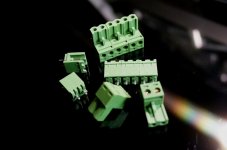
1. 5.08mm terminal blocks socket and connectors
Very easy plug-in/out, more 2P sockets can work as 4P, 6P….flexible
No need special tool to DIY cables
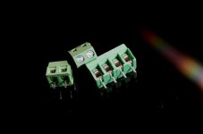
2. 5.08mm terminal blocks
Widely used for power/analog connections, footprint compatible with 5.08 terminal block sockets, more 2P ones can be linked into 4P, 6P…flexible
No need special tool to DIY cables
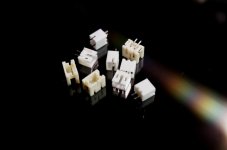
3. PH2.0mm connectors
Compact size, low cost, good for digital siangls
Pin number fixed, not as flexible as terminal block
Difficult to DIY cables because of needs special crimping tool
Please let me know your idea, or your have more options
Once we make a decision, I can go ahead with PCB design.
Regards,
Ian
I’m quite sure we will use u.fl and PH2.0 for digital signals. But we still not decide what connectors are gonna be used for power and analog signals. Here are some options I can think of:
1. 5.08mm terminal blocks socket and connectors
Very easy plug-in/out, more 2P sockets can work as 4P, 6P….flexible
No need special tool to DIY cables
2. 5.08mm terminal blocks
Widely used for power/analog connections, footprint compatible with 5.08 terminal block sockets, more 2P ones can be linked into 4P, 6P…flexible
No need special tool to DIY cables
3. PH2.0mm connectors
Compact size, low cost, good for digital siangls
Pin number fixed, not as flexible as terminal block
Difficult to DIY cables because of needs special crimping tool
Please let me know your idea, or your have more options
Once we make a decision, I can go ahead with PCB design.
Regards,
Ian
Attachments
Power/Analog connector options for the multibit DAC core board
On post #41 it was pointed out the number of power connectors commonly needed by all targeted DACs:
Power connectors 4x2pin:
+Va, GND (analog)
-Va, GND (analog)
+5V, GND (digital)
-5V, GND (digital)
Analog connectors: 4x2pin for 4xPCM channel board.
In total 8x2pin connectors.
1. & 2. 5.08mm terminal blocks
These are really unbeatable as far as ease of use is concerned, however they are quite bulky - 8x2pin would eat up lot of space. I would choose #2 maybe for power input but would go with something smaller for analog output
3. PH2.0mm connectors
I think the fixed pin numbers are not an issue in this case
You don't necessarily need a crimping tool - I don't have one so I simply solder the cable to the contact then squeeze it with a nose plier - indeed it's a tad more difficult to DIY but you have to do it once
Max. AWG24 - for power some would like to use ticker cables but would be OK for analog out
I also suggested
4. EH 2.5mm (JST) connectors
Compact size, low cost, max. AWG22 so it's suitable for power input as well
It has though-hole only package
I would go for either:
a. #2 5.08mm terminal blocks for power in and #3 PH2.0 for analog out
b. #4 EH series all around for power in and analog out
Regards,
Zsolt
Last edited:
Core Board
I think we need low space and easy swap solutions here.
However Zsolt is right about 1. 5.08mm connectors - those are too big, so I would vote for set "b": EH series all around for power and analog out - this allows easier swaping of Core Boards, less chance for mistakes connecting power supply (at least on the end of Core Board ).
Saulius
On post #41 it was pointed out the number of power connectors commonly needed by all targeted DACs:
Power connectors 4x2pin:
+Va, GND (analog)
-Va, GND (analog)
+5V, GND (digital)
-5V, GND (digital)
Analog connectors: 4x2pin for 4xPCM channel board.
In total 8x2pin connectors.
1. & 2. 5.08mm terminal blocks
These are really unbeatable as far as ease of use is concerned, however they are quite bulky - 8x2pin would eat up lot of space. I would choose #2 maybe for power input but would go with something smaller for analog output
3. PH2.0mm connectors
I think the fixed pin numbers are not an issue in this case
You don't necessarily need a crimping tool - I don't have one so I simply solder the cable to the contact then squeeze it with a nose plier - indeed it's a tad more difficult to DIY but you have to do it once
Max. AWG24 - for power some would like to use ticker cables but would be OK for analog out
I also suggested
4. EH 2.5mm (JST) connectors
Compact size, low cost, max. AWG22 so it's suitable for power input as well
It has though-hole only package
I would go for either:
a. #2 5.08mm terminal blocks for power in and #3 PH2.0 for analog out
b. #4 EH series all around for power in and analog out
Regards,
Zsolt
I think we need low space and easy swap solutions here.
However Zsolt is right about 1. 5.08mm connectors - those are too big, so I would vote for set "b": EH series all around for power and analog out - this allows easier swaping of Core Boards, less chance for mistakes connecting power supply (at least on the end of Core Board
).Saulius
TDA1541A DAC
If someone can use any ideas from this, here you go. Did this last September. Powered by the "IanFIFO"
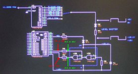
Sounds excellent in spite of the output stage simplicity. Sometimes, simple is better. Using a CCS in 6SN7 plate. Mixed, stepped-down decoupling caps seem to sound better than any single value. Board is 4 layer. Decoupling caps tight to TDA1541 pins. Simple DEM circuit, values in schematic seemed to work best.
To offset DAC current, used a simple pot with resistor to attain 0volts at DAC output. Works great, little or no drift (never measured more than 2mV)
There is a single point digital-analog ground (@0R resistor) with full 3rd layer ground plane.
Using all Salas shunt regulators. Transformer is a custom wound Hammond (6 output) to supply DAC, Digital (FIFO) and tube stage needs. Has flux band to minimize leakage.
For I/V, just using a 50R Rhopoint. The 0.47uF cap, the tube's input resistor, along with the input capacitance of the grid to cathode form a basic LPF with a rolloff of -3.5dB @ 44Khz. Not a lot, but enough to get rid of a good chunk of noise. Seen lots of schemes using coils, etc, but didn't want any unnecessary phase shift. Actually, first "test" PCB used a more elegant LC filter but sounded bad. I think it also defeats the ideology of a NOS DAC design.
I guess there's a lot to pick apart in the design, but OK for a first pass. I'll likely do another with paralleled AD1865N devices. Will shoot for exact digital trace lengths this time around. Was in a bit of a rush as I needed to get it added in with a panel (ok, bad excuse...) so there are a few fixes here and there but mostly good.
Using a double crown/S2 chip it sounds...well, pretty nice. But then, sound is subjective, isn't it?
Should also note that the schematic shows 330R cathode resistors, these are actually 270R - found that value better by experimentation.
Cheers,
Gary
If someone can use any ideas from this, here you go. Did this last September. Powered by the "IanFIFO"
Sounds excellent in spite of the output stage simplicity. Sometimes, simple is better. Using a CCS in 6SN7 plate. Mixed, stepped-down decoupling caps seem to sound better than any single value. Board is 4 layer. Decoupling caps tight to TDA1541 pins. Simple DEM circuit, values in schematic seemed to work best.
To offset DAC current, used a simple pot with resistor to attain 0volts at DAC output. Works great, little or no drift (never measured more than 2mV)
There is a single point digital-analog ground (@0R resistor) with full 3rd layer ground plane.
Using all Salas shunt regulators. Transformer is a custom wound Hammond (6 output) to supply DAC, Digital (FIFO) and tube stage needs. Has flux band to minimize leakage.
For I/V, just using a 50R Rhopoint. The 0.47uF cap, the tube's input resistor, along with the input capacitance of the grid to cathode form a basic LPF with a rolloff of -3.5dB @ 44Khz. Not a lot, but enough to get rid of a good chunk of noise. Seen lots of schemes using coils, etc, but didn't want any unnecessary phase shift. Actually, first "test" PCB used a more elegant LC filter but sounded bad. I think it also defeats the ideology of a NOS DAC design.
I guess there's a lot to pick apart in the design, but OK for a first pass. I'll likely do another with paralleled AD1865N devices. Will shoot for exact digital trace lengths this time around. Was in a bit of a rush as I needed to get it added in with a panel (ok, bad excuse...) so there are a few fixes here and there but mostly good.
Using a double crown/S2 chip it sounds...well, pretty nice. But then, sound is subjective, isn't it?
Should also note that the schematic shows 330R cathode resistors, these are actually 270R - found that value better by experimentation.
Cheers,
Gary
Attachments
Last edited:
I am kind of late to this thread but I would really like to suggest three must have versions.
1. PCM1704, that last most advanced R2R, still available in real K version from reputable sources. And they will probably not obsolete it for years. Its irreplaceable by high profile instrumentation customers. Allows the most advanced oversampling algorithm's since its accepts 24 bit.
2. AD1862 - Favorite of insiders like Jocko because of its architecture which is too complicated for me to remember but it is considered a true R2R. It was Analog Devices best effort at R2R and had technology that will never be seen again. They sound damn good too.
3. I like the PCM56K and its "competitor" the AD1865K as they are nice and simple, real time software playback never offers 20 bit dither real time oversampling is dicey, So I just prefer the PCM56K. Both have the advantage of high voltage compliance which makes the analog stage much easier. But then again they are so simple a PCB may not even be needed, so lower priority maybe ?
I am Hesistant on this one : TDA1541, it is very special, multi-bit but not R2R. The hesistation is to truly implement it right require so many tricks and secrets that it may be beyond the scope of this project. TDA1541 enthusiasts will never be happy with whatever we come up with I mean we have a 500 post thread on building a TDA1541 board with absolutely no consensus.
So basically a PCM1704k based board is the best choice, no black market. 24 bit no truncation. You can order it from digikey and know its really a K. The analog stage is tough but more choices are appearing.
All in all I think this is a fantastic project and think there will be some real eye openers compered to the S-D dac's that have been slammed down our throats for years.
Afterall I remember saying early on one advantage to this whole project is comparing multibit DAC's of all kinds and makes, fun, fun, stuff awaits.
One question I have the dual clock version of the Fifo, am I shooting myself in the foot not getting the Si570 board ?
Thanks
1. PCM1704, that last most advanced R2R, still available in real K version from reputable sources. And they will probably not obsolete it for years. Its irreplaceable by high profile instrumentation customers. Allows the most advanced oversampling algorithm's since its accepts 24 bit.
2. AD1862 - Favorite of insiders like Jocko because of its architecture which is too complicated for me to remember but it is considered a true R2R. It was Analog Devices best effort at R2R and had technology that will never be seen again. They sound damn good too.
3. I like the PCM56K and its "competitor" the AD1865K as they are nice and simple, real time software playback never offers 20 bit dither real time oversampling is dicey, So I just prefer the PCM56K. Both have the advantage of high voltage compliance which makes the analog stage much easier. But then again they are so simple a PCB may not even be needed, so lower priority maybe ?
I am Hesistant on this one : TDA1541, it is very special, multi-bit but not R2R. The hesistation is to truly implement it right require so many tricks and secrets that it may be beyond the scope of this project. TDA1541 enthusiasts will never be happy with whatever we come up with
I mean we have a 500 post thread on building a TDA1541 board with absolutely no consensus.So basically a PCM1704k based board is the best choice, no black market. 24 bit no truncation. You can order it from digikey and know its really a K. The analog stage is tough but more choices are appearing.
All in all I think this is a fantastic project and think there will be some real eye openers compered to the S-D dac's that have been slammed down our throats for years.
Afterall I remember saying early on one advantage to this whole project is comparing multibit DAC's of all kinds and makes, fun, fun, stuff awaits.
One question I have the dual clock version of the Fifo, am I shooting myself in the foot not getting the Si570 board ?
Thanks
TDA1541
Thank you for your opinion.
It looks like you are speaking on behalf of all TDA1541 enthusiasts.
Unfortunately for TDA1541 fans you are representing, we still have here some consensus
And I hope we will have Core Board for TDA1541 on level of Red Baron (which is OK for many TDA1541 fans, including myself, but is little bit too long, especially if you are not going to use I/V part).
Best wishes
Saulius
I am Hesistant on this one : TDA1541, it is very special, multi-bit but not R2R. The hesistation is to truly implement it right require so many tricks and secrets that it may be beyond the scope of this project. TDA1541 enthusiasts will never be happy with whatever we come up with
Thanks
Thank you for your opinion.
It looks like you are speaking on behalf of all TDA1541 enthusiasts
. Unfortunately for TDA1541 fans you are representing, we still have here some consensus
And I hope we will have Core Board for TDA1541 on level of Red Baron (which is OK for many TDA1541 fans, including myself, but is little bit too long, especially if you are not going to use I/V part).
Best wishes
Saulius
Hi all,
if anyone was interested in the custom Laptech crystal
http://www.diyaudio.com/forums/grou...hronous-i2s-s-pdif-fifo-kit-group-buy-70.html
please add your name in the wish list at
http://www.diyaudio.com/forums/digital-line-level/203511-any-good-tda1541a-dac-kit-96.html
The minimum orderable quantity from Laptech is 5 pcs for each frequency.
When that quantity will be reached I ask Laptech for a quote.
Andrea
Hi all,
if anyone was interested in the custom Laptech crystal
http://www.diyaudio.com/forums/grou...hronous-i2s-s-pdif-fifo-kit-group-buy-70.html
please add your name in the wish list at
http://www.diyaudio.com/forums/digital-line-level/203511-any-good-tda1541a-dac-kit-96.html
The minimum orderable quantity from Laptech is 5 pcs for each frequency.
When that quantity will be reached I ask Laptech for a quote.
Andrea
As promised, the list of interest is started.
http://www.diyaudio.com/forums/digi...-jitter-crystal-oscillator-4.html#post4057057
AD1865 core board
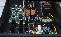
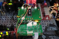
I had a pretty long pause on this hobby but finally I ensemble the AD1865 core board Ian kindly sent me almost three years ago.
It may sound repetitious but it indeed improved the sound of the whole system - be it the u-fl cabling of signals or the carefully designed PCB don't know but the imaging of the system got better by a lot (I mean it). If I knew there will be such change I might have done it before.
Thanks Ian again for these beautiful PCBs!
Since you sent me more, with your permission, I would donate 4 PCBs for whomever wants to pair them with the I2S-PCM board.
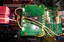
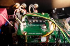
Here comes some pictures of the board, what you see around the FIFO stack are Salas regulators, Pass D1 with huge 10uF Wima MKP caps and a relayed volume control.
I had a pretty long pause on this hobby but finally I ensemble the AD1865 core board Ian kindly sent me almost three years ago.
It may sound repetitious but it indeed improved the sound of the whole system - be it the u-fl cabling of signals or the carefully designed PCB don't know but the imaging of the system got better by a lot (I mean it). If I knew there will be such change I might have done it before.
Thanks Ian again for these beautiful PCBs!
Since you sent me more, with your permission, I would donate 4 PCBs for whomever wants to pair them with the I2S-PCM board.
Here comes some pictures of the board, what you see around the FIFO stack are Salas regulators, Pass D1 with huge 10uF Wima MKP caps and a relayed volume control.
Attachments
Last edited:
Thanks, the only special component might be the X2Y capacitor from the bottom side: DigiKey part: 311-1245-1-ND but I better attach the schematics (it's from you but others might need it).Thanks vzs,
really very very nice indeed. Since you are happy with the result, I'm gonna build mine soon. Is there any component special? What's your I/V stage?
Regards,
Ian
My I/V is Pass Labs D1 fed by Salas regs.
I think your ESS dac uses it's cousin, the "New Take on the Classic Pass Labs D1" from Owen.
The digital side is powered from the PCM-I2S board like in the image.
Errata: this I2S-PCM version has incorrect silk on this output - the highlighted part
Regards,
Zsolt
Attachments
Last edited:
- Status
- This old topic is closed. If you want to reopen this topic, contact a moderator using the "Report Post" button.
- Home
- Source & Line
- Digital Line Level
- Multibit DAC core boards coupled with I2S-PCM driver board