Not yet, I don't have a scope and cannot do the trimming without.Hi vzs,
Have you tried the MSB trimmers?
Do you tried it and it helped noticeably?
Hi Vzs & Ian,
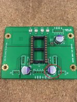
Thanks for the ad1865 core board and the layout is indeed very nice. While I was populating the PCB, I realized there is an incorrect silk for C5 polarity. Shouldn't the Vcc- be connected to the negative polarity of the capacitor?
Regards,
Cheng
Thanks for the ad1865 core board and the layout is indeed very nice. While I was populating the PCB, I realized there is an incorrect silk for C5 polarity. Shouldn't the Vcc- be connected to the negative polarity of the capacitor?
Regards,
Cheng
I had a pretty long pause on this hobby but finally I ensemble the AD1865 core board Ian kindly sent me almost three years ago.
It may sound repetitious but it indeed improved the sound of the whole system - be it the u-fl cabling of signals or the carefully designed PCB don't know but the imaging of the system got better by a lot (I mean it). If I knew there will be such change I might have done it before.
Thanks Ian again for these beautiful PCBs!
Since you sent me more, with your permission, I would donate 4 PCBs for whomever wants to pair them with the I2S-PCM board.
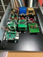
Here comes some pictures of the board, what you see around the FIFO stack are Salas regulators, Pass D1 with huge 10uF Wima MKP caps and a relayed volume control.
Attachments
Thank you Vzs and Ian for the work putting the board together and for giving us few fortunate diyers a board. Also thank you Vsolt for shipping the board at no charge to us.
I haven't populated my board yet but after reading Cheng's post, I looked at the schematic and the board and it does appear to me that the polarity of the capacitor on the -5v analog supply line is backwards.
I haven't populated my board yet but after reading Cheng's post, I looked at the schematic and the board and it does appear to me that the polarity of the capacitor on the -5v analog supply line is backwards.
Last edited:
Thank you guys for pointing this out, C5 is indeed reversed in the schematics and thus the silk is incorrect, should be reversed.Hi Vzs & Ian,
Thanks for the ad1865 core board and the layout is indeed very nice. While I was populating the PCB, I realized there is an incorrect silk for C5 polarity. Shouldn't the Vcc- be connected to the negative polarity of the capacitor?
Regards,
Cheng
I was lucky the electrolytic did not exploded as I was using it reversed.
Zsolt
Thank you Vzs and Ian for the work putting the board together and for giving us few fortunate diyers a board. Also thank you Zsolt (vzs) for shipping the board at no charge to us.
I haven't populated my board yet but after reading Cheng's post, I looked at the schematic and the board and it does appear to me that the polarity of the capacitor on the -5v analog supply line is backwards.
Hi vzs,
I apologize for spelling your name wrong in post #89. I edited it once and still didn't catch the second mistake.
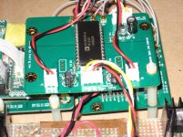
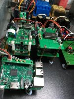
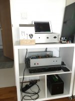
Here are pictures of my board and the dac system that it is attached to.
The construction went smoothly except I applied too much solder paste on C8 (X2Y cap) and I ended up with a short when I checked it. With smd components I always order extra so I redid it with less paste and all was fine.
I also noticed that the electrolytic caps that I ordered (Panasonic FK series) were a lot smaller than the caps on your board. It was then that I realized that I didn't check for fancier caps such as aluminum organic polymers when I ordered the caps. In the end I checked my parts box I found one used Black Gate 22uf which I added to the digital supply and two Panasonic FR 100uf to the analog supply just to feel good.
For power, the digital supply is from the I2S-PCM board as you had done. The two analog supplies are from my diy veroboard/copper foil TDA1541a board that I had done years ago and that I still use. I took off the TDA1541a and took the +5 and -5 volts off the chip supply socket pins. The I2S-PCM board power is also from this board, but from a now unused socket that was previously used for a reclocking chip. I built this board a few years before Ian's fifo was a reality. All of the supplies on the board comprise LM317 pre-regulator, LM317 constant current source, ferrite rings with choke in between, TL431 regulator, and various capacitors including smd at the power pins. The supplies (and veroboard/copper foil board) were based on Thorsten Loesch's tips and recommendations in this diyaudo thread:
http://www.diyaudio.com/forums/digital-line-level/203511-any-good-tda1541a-dac-kit-36.html
For IV, I used a 50 ohm resistor paralleled with a 10nf capacitor. I didn't want to use a higher value resistor because the output goes to a 5842 tube stage that I use with my TDA1541a, and the 50 ohms give enough voltage so that the 5842 output is not too high.
The AD1865 chip was purchased on ebay from China. It is labeled as AD1865N-K and the cost with shipping included was less than 17 USD. I don't know if it is a genuine N-K or not but it works. It seems to be a fairly low price for a N-K and there seems to be a lot of them available on ebay.
After listening to this board for a day, I think that it is similar in sound to my TDA1541a. I don't know whether I can say that one is better than the other. I can say that I enjoy the music from both boards and that is all that matters to me.
Again, thank you for the board.
Attachments
Hi Vzs & Ian,
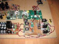
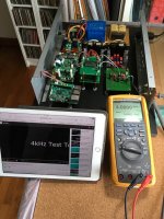
Managed to get the AD1865 core board to sing with the following setup.
Rpi>Ian Fifo>Ian Isolator>Ian Dual Clock>Ian PCM>AD1865 Core Board>Opamp IV
Still trying to figure out what is wrong with the previous Kali setup, but this confirmed that the AD1865 Core Board is good and thank you both again for the wonderful creation")
Next on the test bench:
1. Triple AD844 IV
2. OPA861 IV
3. Sen & Cen IV
Cheng
Managed to get the AD1865 core board to sing with the following setup.
Rpi>Ian Fifo>Ian Isolator>Ian Dual Clock>Ian PCM>AD1865 Core Board>Opamp IV
Still trying to figure out what is wrong with the previous Kali setup, but this confirmed that the AD1865 Core Board is good and thank you both again for the wonderful creation
Next on the test bench:
1. Triple AD844 IV
2. OPA861 IV
3. Sen & Cen IV
Cheng
Attachments
Hi Vzs & Ian,
Managed to get the AD1865 core board to sing with the following setup.
Rpi>Ian Fifo>Ian Isolator>Ian Dual Clock>Ian PCM>AD1865 Core Board>Opamp IV
Still trying to figure out what is wrong with the previous Kali setup, but this confirmed that the AD1865 Core Board is good and thank you both again for the wonderful creation
Next on the test bench:
1. Triple AD844 IV
2. OPA861 IV
3. Sen & Cen IV
Cheng
Hi Cheng,
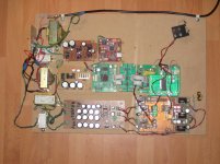
Very well finished DAC. Good and clean setup. Good job!
I'm interested in your I/V, if it is possible, please give us some information.
BTW, you have an oscilloscope on your cell phone? What's that?
Good weekend.
Ian
Hi Ian,
Thanks for the compliment. It is just an quick simple dual opamp iv stage that I have done up to test on the dac. Nothing fancy.
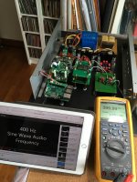
The ipad is use to stream the frequency signal from youtube (via volumio) to rpi for testing purpose (to confirm the output) before connecting to amplifier & speakers.
Cheers
Thanks for the compliment. It is just an quick simple dual opamp iv stage that I have done up to test on the dac. Nothing fancy.
The ipad is use to stream the frequency signal from youtube (via volumio) to rpi for testing purpose (to confirm the output) before connecting to amplifier & speakers.
Cheers
Hi Ian,
Thanks for the compliment. It is just an quick simple dual opamp iv stage that I have done up to test on the dac. Nothing fancy.
The ipad is use to stream the frequency signal from youtube (via volumio) to rpi for testing purpose (to confirm the output) before connecting to amplifier & speakers.
Cheers
Thanks Cheng, can you give the links to the test signals? Very good idea.
Ian
Hi Ian,
I not sure if anyone does this, but i find it useful and convenient to check the output via DMM before connecting to the system. Below are the link for all the test tone. plenty from others too.
https://www.youtube.com/channel/UCRwHD3nEPeOQehdfD_qTVHQ/videos
Cheers
I not sure if anyone does this, but i find it useful and convenient to check the output via DMM before connecting to the system. Below are the link for all the test tone. plenty from others too.
https://www.youtube.com/channel/UCRwHD3nEPeOQehdfD_qTVHQ/videos
Cheers
AD1865 MSB trim
I recently acquired a Focusrite Scarlett 2i2 USB interface to use in tweaking my stereo system. In conjunction with software such as REW, Arta, RMAA, I have used it to tweak my speaker levels while biamping and adjusting bias for lowest distortion in my recently completed Sony VFET Luminaria preamp.
My latest tweak has been to my AD1865 dac that was built with the Ian/vzs board. My version has a very simple iv converter - a 500 Ohm diy wire wound resistor. I had purchased the AD1865 chip nearly a year ago from an eBay merchant in Hong Kong for about US $17. It was marked as AD1865N-K, but whether it is a N-K grade chip or not is debatable.
I connected the dac output to the Focusrite, played a -60dB 1kHz sine signal and measured the THD and THD+N using the FFT spectrum analysis in Arta on my laptop for some baseline numbers.
I installed the two resistors and one trim pot per channel as required for the MSB trim circuitry, and tweaked the trim pot for each channel. The results were only a small reduction in THD+N in both channels but the decrease in THD was significant. The left channel had a decrease of 32% and the right channel 28%. To make the numbers seem even more impressive, the untrimmed THD was 48% higher in the left channel and 40% higher in the right channel when compared to the trimmed values.
I suppose that the gains from MSB trimming will vary depending on the manufacturing tolerances of each individual chip, and also depending on its actual grade as marked at the factory. However I attained some major gains with my chip.
Sonically, the soundstage has expanded with better side to side fill and better depth behind the speakers, and images have become more cohesive, Live recordings seem more realistic, especially the crowd noise between songs. Overall, another step closer to live. I am really, really enjoying this tweak.
This sounds impressive! I'm using mine without trimming because I neither have the equipment nor the drive to tweak my system any more, found another hobby/work, A.I. related , that takes all my time.
But seeing these results I will consider squeezing some time for it. Thanks.
, that takes all my time.But seeing these results I will consider squeezing some time for it. Thanks.
- Status
- This old topic is closed. If you want to reopen this topic, contact a moderator using the "Report Post" button.
- Home
- Source & Line
- Digital Line Level
- Multibit DAC core boards coupled with I2S-PCM driver board