i did a quick and very dirty job on differential tda1541 design tonight. this is my first foray into eagle so please do keep my feelings in consideration, heh.
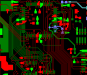
the reason for cs8412 being in the middle, oversized decoupling caps, double row smoothing caps... well, call it a mass appeal. i tried to completely separate digital and analogue section.
you can obviously see salas shunts and the coax input is of peter daniels' design.
i have no skill and time for optimal layout and all. if the circuit should work, that's good enough for me to do a test print.
the output will be 1:20 trafo. suggestions for an active stage would be appreciated. thank you all.
http://postimg.org/image/5jblakfs7/full/
free image hosting
the reason for cs8412 being in the middle, oversized decoupling caps, double row smoothing caps... well, call it a mass appeal. i tried to completely separate digital and analogue section.
you can obviously see salas shunts and the coax input is of peter daniels' design.
i have no skill and time for optimal layout and all. if the circuit should work, that's good enough for me to do a test print.
the output will be 1:20 trafo. suggestions for an active stage would be appreciated. thank you all.
http://postimg.org/image/5jblakfs7/full/
An externally hosted image should be here but it was not working when we last tested it.
free image hosting
Last edited:
Could just be that you're giving off mixed messages. On one hand, you want comments, but on the other hand you 'have no time for optimal layout' - thus people who have experience of doing this are going to steer clear. Its time consuming to examine another's layout so they'd want more reassurances their suggestions will get implemented.
of course i would like to implement them eventually but as for now i just would like to know if there's any mistakes that are glaringly obvious.
in short i'd like a quick fixie if the circuit needs it
(and high mind suggestions for future artwork.)
right now i'm most concerned about all the vias jumping layers. is that a ticket for ground loop?
here's a little edit i did with grundig dem reclock implemented.
http://postimg.org/image/5qf7gk0u7/full/
in short i'd like a quick fixie if the circuit needs it
(and high mind suggestions for future artwork.)
right now i'm most concerned about all the vias jumping layers. is that a ticket for ground loop?
here's a little edit i did with grundig dem reclock implemented.
An externally hosted image should be here but it was not working when we last tested it.
http://postimg.org/image/5qf7gk0u7/full/
Last edited:
Just a couple of quick suggestions....
You should limit your wire angle to 45 degree increments.
Curved traces are fine to use.
Where two traces meet, should be limited to 90 degrees.
If two traces meet at more acute angles, chemicals can get
trapped and cause trace failure.
The polygon command can be used to make thick traces as well as
filled planes.
thank you gents.
tazzz, digital and analogue has completely separate grounds. i thought that would be ok but smarter suggestion would be appreciated.
is it worse or impossible to share regulators? i've been doing that for differential 1543 with pleasant results. for 1541 that would mean 6 regulators *gasp
tazzz, digital and analogue has completely separate grounds. i thought that would be ok but smarter suggestion would be appreciated.
is it worse or impossible to share regulators? i've been doing that for differential 1543 with pleasant results. for 1541 that would mean 6 regulators *gasp
To illustrate the comments on routing here is a picture that illustrates 90/45 degree corners and neat routing. DONT use curved traces, they are hard to do and serve no purpose what so ever other than make layout even harder.
When I said start again, the best way to get proficient at PCB design is to practice.
Again for best signal integrity ALL digital lines should run over a contiguous ground plane to provide the best return current path.
A link that explains the reasons...
http://www.x2y.com/filters/TechDay0...log_Designs_Demand_GoodPCBLayouts _JohnWu.pdf
Attachments
- Status
- This old topic is closed. If you want to reopen this topic, contact a moderator using the "Report Post" button.
- Home
- Source & Line
- Digital Line Level
- please critique my pcb