Anyone knowing the exact power requiremts of the Weiliang ES9018 Board?
It is described here
http://www.diyaudio.com/forums/digi...diy-es9018-hi-end-usb-dac-27.html#post4712466
and here is the schematic
http://www.diyaudio.com/forums/atta...i-end-usb-dac-es9018-schematicdiyhifishop.pdf
I measured 4.3mA on the positive +15V rail measuring voltage across R5A
of the analog power supply. In real life, with NE5532 opamps implemented it is +12V BTW.
Nevertheless, 4.3mA seems strange - the the two opamps consume 8mA each.
The reason why I am asking: There are restictions in space for the transformer. This is why I would like to keep them as small as possible...
Thanks, but 3x10W = 30VA is way too much. (if it is 10VA for each rail, it would be a total of 40VA)
Especially when the two 9V lines just supply the clock and DAC.
Again, I have restrictions in space an will not use an additional enclosure.
I am not talking about over-engineering here. Just sensible values.
As one example, I have some second-generation CD-Players at home. Some of them, using fancy stuff like linear motors
do not need more than a total of 15W - one "High End" Nakamichi just 25W, one Audio Alchemy "DAC in the Box" power supply is rated 8W for the primary and just 150mA for the secondary.
So, were those machines from the mid-eighties from a time of power-restrictions? I doubt so.
The ES9018 chip consumes a total 70mA. Thus I assume values like 250mA or 2.25VA just for the DAC would meet the demand...?
At which points besides R5A can I measure the current? My multitester does not seem to be that accurate for direct current measurement...
Thanks,
Salar
Then 6W if space is problem ...38x45mm i have wrote +-15V/10w not 2x10w and no complication ...
and use 2v7,5v 6W for digital part and 2x15V/6w for analog part around 200ma. If transformers becomes hot than use larger ones. Current can be measured between the line or voltage drops on resistors in the line. Splitting will be harder at your design...it is easier when design has installed chokes or ferrite beads than you can switch to resistor and measure current.
and use 2v7,5v 6W for digital part and 2x15V/6w for analog part around 200ma. If transformers becomes hot than use larger ones. Current can be measured between the line or voltage drops on resistors in the line. Splitting will be harder at your design...it is easier when design has installed chokes or ferrite beads than you can switch to resistor and measure current.
Last edited:
Thanks!
In my board, the DC supply voltage is for the 4 NE5532 opamps is even only
+/-12V.
I am using a transformer from a broken CD-Player for testing. Even the secondary 4V, made for driving the filaments of a VFD are sufficient to feed the clock.
Heatsinks do not become warm...
In my board, the DC supply voltage is for the 4 NE5532 opamps is even only
+/-12V.
I am using a transformer from a broken CD-Player for testing. Even the secondary 4V, made for driving the filaments of a VFD are sufficient to feed the clock.
Heatsinks do not become warm...
There is a hum that annoys me - to put things straight, if I was to listen to the hum with music on, the noise wold blast me through a wall. I used a silent track for checking and ramped my 40W amp all the way up
For comparison, I used a Sony CDP-X5000 and Philips CD304MKII as references.
With the Sony some hiss is audible (sound almost like a mic preamp) To my surprise the older, 2nd generation CD304MKII is even more silent than the Sony.
Intersting, amachine with only one supply for servo, DAC and output stage.
Noisewise the Philips is beaten beaten by a Buffalo DAC with Placid supplies. The Buffalo is dead silent.
Anyway, the hum of te Weiliang DAC is a multiple of 50hz, I assume around 100hz sounds almost like a ground loop.
Again, it would be completely masked by the music, I assume it is around -70dB (It is almost as loud as a -60db Testtone)
Especially when the power supply for the xtal gets hooked to a transformer, the hum reaches this level.
Checked the caps, one wrong cap for the LT1085´s output feeding the Weiliangs xtal.
47µF printed on the board, in fact 1µF installed, the LT1085 (Fixed version btw) datasheet demands 150µF on the output.
The 1085 is followed by a 3.3V(?) regulator, name was mentioned in this thread. Changed the 1µF to 470UF, hum did not change at all.
The Sony and the Philips use ordinary 78xx/79xx regulators, between 20 and 30 years old...
Is low ripple noise a weakness of the LT1085?
Last edited:
I did try to reduce the -70dB hum by using only one rectifier circuit and one 5V
voltage regulator. Normally it is two of them with their own rectifiers . One LT1085 rateted 3A is for all the voltages the ES9018 needs, one LT1086 is for the Xtal.
To my surprise the DAC does not lock to SPDIF when only the 1085 feeds all following voltage regulators.
When only the +/-15V supplies (shunt regulated I assume) are powered, the DAC is silent.
When the 1085 and 1086 are powered, the hum comes into play.
I am using one Transformer with four secondaries
Tried them galvanically connected as well as galvanically isolated, no change.
Any ideas how to reduce the hum?
Will a 7805 suppress ripple around 100hz better than a 1085/86?
Will this help? And how?
But the board has fixed regulators:
But the board has fixed regulators:
An externally hosted image should be here but it was not working when we last tested it.
Swapped the two LT1085 today to 7805 voltage regulators. They have lesser noise around 100hz. Ripple/hum noise was now a tad more silent.
Only the supply for the Xtal seems to produce noise. When it is not connected to the transformer, the DAC is dead silent. Again, speaking of noise/hum around -70dB here.
Rectification for both voltage regulators is separated. Having both voltage regulators with their smoothing capacitors hooked on one rectification circuit only (a common design i see in many CD-Players or DACS) produces more noise. The hum is now accompanied by a sawtooth like overtone.
Having both rectifiers hooked on one transformer secondary produces the same sawtooth like noise. Only galvanically seperated secondaries make the sawtooth like sound disappear, but the hum still remains!!
Also the grounds of the xtal and DAC circiut do not seem to be seperated so
I am really confused.
Another strange effect. One secondary of the transformer only produces 3.8VAC. So a little more than 5V after rectification. Plugged in to the noisy supply, by a "miracle" the XTAL gets power and works.
Having both circuits hooked one one transformer secondary (in fact two galvanically connected secondaries) also stresses the second 7805
that supplies the DAC. It becomes very hot and runs cooler with galvanically isolated secondaries...
The circuit that makes problems starts with "AC-IN CON2"...
Attachments
Last edited:
The Oppo seems to have a small amount of circulating current on ground and the regulators pick that up on the adjustment pin. The Oppo chassis is the ground and is grounded together in places creating this loop. You can get the old 78 and 79 series regulators to work ok but you need really low ESR caps to filter out the noise.
I been want to design changes on the Oppo but my DAC and Transport have less noise
but the Oppo great for Tidal. I wondered if they worked out the flaws in the new 205.
Cheers
I been want to design changes on the Oppo but my DAC and Transport have less noise
but the Oppo great for Tidal. I wondered if they worked out the flaws in the new 205.
Cheers
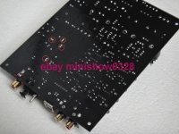
Connecting the ground planes beyond the DAC in the red circled area reduces the hum a lot. They are connected somewhere anyway but I assume return paths become shorter by doing so. Still not perfect, but not very much louder than other DACs.
No hints for what the pads are good for and of course no support from the seller whose name is prominently featured on the attached photo.
I assume the marked areas are not for shortening but for smd caps and proper decoupling of the ground planes.
Anyone any idea what the values might be?
All the best,
Salar
Attachments
I need your advice!
DAC ES9018 DAC Amanero (MINI SHOW) ES9018 DAC with MUSES8920*2+LME49990*2+Display + Amanero USB card L1611-10
When replacing the OPAMP in the I/U one MUSES8920 I put inverted key 180 degrees, After 10 seconds I realized it and turned off the device.
Now is not working the right channel no sound. OPAMPs now the norm and I/U and buffer (reversed - left is right, put others, both MUSES8920 put in another DAC - they are OK).
And this "Amanero ES9018 DAC" in right channel silence. The voltage on the OPAMPs in both channels in normal. On the Board with operas clean, nothing burnt, no smell of fire. The main PCB is also normal.
Tell me, what else needs to be check and change, repair, soldering? Tell me what to do.
Need some advice....
Are these boards from Mshow worth buying? With the ES9038pro chip.
In comparison to the other little DACS out there.
Like the Melokin DA
Topping DX7s
Pro-ject pre box digi s2?
Considering the price there is so little info or reviews about it.
You would think everybody wants to try it at least. Before buying a 1000 Dollar DAC.
Last edited:
Coming back to the "Black Board" ES9018 Dac shown in Post #291.
I still have the hum problem- some sawtooth like noise around 100hz I guess - it can be heard with no signal and with the amp ramped up. I guess it must be around -80dB.
So not really annoying but the hum is only there, when the circuitry of the crystal clock is powered by its dedicated AC input
The Dac has 3 voltage circuits, for the output stage, DAC and clock.
Again witout the clock powered, the DAC is completely silent. With the clock (crystal) powered from its dedicated AC-Input, the hum is there.
Powering the Clock and output stage only makes the hum even more audible.
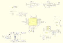
I got the schematic attached from the seller.
In the schematic there are differend ground planes for the the DAC, clock and output stages.
The ES9018 and its power supply are connected to the classical gnd, the triangle marked with stripes.
But the analog output stages, clock and their psu are connected to an equipotential - an "empty" triangle-what does this mean in practice?
Are those different grounds connected at one point - or not connected at all?
Measuring with the voltmeter all circuitry seems to share the same ground,
i.e measuring between the crystals housing to the Dac´s grounds or the output jacks. Something wrong here - or normal?
All the best,
Salar
I still have the hum problem- some sawtooth like noise around 100hz I guess - it can be heard with no signal and with the amp ramped up. I guess it must be around -80dB.
So not really annoying but the hum is only there, when the circuitry of the crystal clock is powered by its dedicated AC input
The Dac has 3 voltage circuits, for the output stage, DAC and clock.
Again witout the clock powered, the DAC is completely silent. With the clock (crystal) powered from its dedicated AC-Input, the hum is there.
Powering the Clock and output stage only makes the hum even more audible.
I got the schematic attached from the seller.
In the schematic there are differend ground planes for the the DAC, clock and output stages.
The ES9018 and its power supply are connected to the classical gnd, the triangle marked with stripes.
But the analog output stages, clock and their psu are connected to an equipotential - an "empty" triangle-what does this mean in practice?
Are those different grounds connected at one point - or not connected at all?
Measuring with the voltmeter all circuitry seems to share the same ground,
i.e measuring between the crystals housing to the Dac´s grounds or the output jacks. Something wrong here - or normal?
All the best,
Salar
Attachments
Have you tried using the other 9v winding from the transformer, just to rule that out?
You could try snubbing the diodes with a .1uf cap, just to see if it makes any difference, after all, maybe the diodes are bad. I have had some get noisy from too much heat during soldering.
The 7805 regulators are cheap, maybe just try replacing it to see if that is causing the noise.
I’m assuming you don’t have a scope...
Hello phase,
thanks for the answer!
I have a scope and can try to make the hum/buzz visible.
I also swapped windings with no difference.
Again, connecting CON2 (see schematic) to a transformer will introduce the buzz. With CON1 and CON3 the Dac is silent.
With CON2 (crystal) and CON1 (output stage) connected to a transformer the buzz is even louder
This is why I thought of some error in grounding.
Changed the regulators but - well - no change.
You mean the recifier diodes?
Not checked / swapped yet. Donn´t think it is them as I can produce more hum by leaving one rectifier circuit out
I cannot display the hum on the scope, I assume with 5mV on the scope and the probe set to x10 the measuring range is 0.5mV.
And again, the buzz sounds like the good old guitar amp´s open ground...
And again, very quiet but probably avoidable as the two other cicuits do not hum at all. This brings me back to the schematic:
Do the ground planes of Clock and DAC have to be seperated?
And again, the buzz sounds like the good old guitar amp´s open ground...
And again, very quiet but probably avoidable as the two other cicuits do not hum at all. This brings me back to the schematic:
Do the ground planes of Clock and DAC have to be seperated?
Just checked the GND connections between clock crystal and circuitry on my Buffalo II DAC - greatest DAC I own so far -
ground of crystal and the rest of the circuitry are connected. Checked also to bypass the "soft" grunding of the chinese / Weiliang DAC´s circuitry
and connect it to the amplifiers ground - but this this even made the hum more audible.
ground of crystal and the rest of the circuitry are connected. Checked also to bypass the "soft" grunding of the chinese / Weiliang DAC´s circuitry
and connect it to the amplifiers ground - but this this even made the hum more audible.
Powering CON2 produces the hum... The decoupling capacitors of CON2 and 3 are connected to an equipotential in the schematic,
as well as the crystal oscillator and the toslink receiver - CON2 and the complete rest of the circuitry are not
So i assume the equipotential symbols are just nonsense...
as well as the crystal oscillator and the toslink receiver - CON2 and the complete rest of the circuitry are not
So i assume the equipotential symbols are just nonsense...
- Status
- This old topic is closed. If you want to reopen this topic, contact a moderator using the "Report Post" button.
- Home
- Source & Line
- Digital Line Level
- DIY ES9018 Hi-end USB DAC