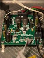
Much improved numbering and silk screen. You have also managed to include at least one curious "feature": R8 is written mirrored, but then again it looks like you have it underneath. I wonder how that came about. The long ES9023 are very cool. J2 is another nice idea.
R8 and also R141 and R151 are indeed on the bottom side of the board, thus the mirrored names
") . Now that I have received the boards I realized that my supplier puts silkscreen on both sides without extra charge
. Now that I have received the boards I realized that my supplier puts silkscreen on both sides without extra charge R8 is underneath to gain some space for a filmcap as an alternative to the C701 Elcap (or Oscon,...).
To be honest, I would indeed love to have more layers available. However having the overall cost in mind I think for the ES9023 the two layer board is a realy good go (I managed to realize an uninterupted GND layer
). For a next project (ADC with RIAA) I will definately have to switch to 4 layers... Currently there is no groupbuy so there is no waiting list. I have ordered some boards and will do tests within a closed group of a few people. I have some spare boards that I can provide to some of the current beta tester (I will contact you by PM!).
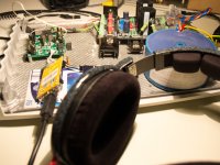
New board up and running
I'm just listening to the new board and I am very pleased with the sound. Compared to the first Version I have the feeling of improved timing and clarity. But most of all I love the timbre - voices have great colour and cymbals sound clear and have body (mmh, I am really not the best at describing my impressions).
I will send out some betaboards soon (all boards are reserved, sorry) and quite a few people will listen to the DAC at the Frickelfest. Looking forward to hear some comments from other listeners
Best regards, Daniel
I'm just listening to the new board and I am very pleased with the sound. Compared to the first Version I have the feeling of improved timing and clarity. But most of all I love the timbre - voices have great colour and cymbals sound clear and have body (mmh, I am really not the best at describing my impressions
).I will send out some betaboards soon (all boards are reserved, sorry) and quite a few people will listen to the DAC at the Frickelfest. Looking forward to hear some comments from other listeners
Best regards, Daniel
Attachments
Build went very well. The new pad layout for the ES9023 proved to be very convenient to add decoupling Cs very close to the IC. I used 10nF NPO + 2µF X7R (0603) directly at the IC for AVCC and NEG supply.Fantastic Daniel! Did the build go well? spacing? silk scenes? polarity?
Silkscreen is correct this time
It's the miniSTREAMER from miniDSP, a TE7022 based USB to I2S/SPDIF converter.I don't recognize your USB board? It looks nice and even smaller than the Amanero. Which one is it?
Due to the synchronous USB transfer it seems to be a little outdated if you follow the discussions here in the forum but I think it's a decent performer. It will probably benefit a lot from the devided MCLK from my ES9023 board as well as from external power supply (not USB powered). I'll try that later. Currently I am terribly busy
@curryman Is there a way to tap the DAC XO on the v2 and send it to RCLK on an Acko Isolator/Re-clocker board for what Acko is calling pseudo-sync mode? Otherwise, I'd have to go with an external clock like Acko's new clock board and send that to the re-clocker which then would feed MCLK on the DAC board. Acko is calling this sync mode. I'm assuming I'd leave the XO off the DAC at this point. What other parts would I leave off? Also what is the MCKL:4 used for? Is it for S/PDIF clocking?
Otherwise, I'm thinking of doing Async mode and going with isolation only from the Acko board. This mode would be best if I only want to go for isolation.
Otherwise, I'm thinking of doing Async mode and going with isolation only from the Acko board. This mode would be best if I only want to go for isolation.
There is a MCLK In/Out header on board that could be used to feed external circuits with onboard XO signal. Just place a suitable R at J2 position (0603 case).@curryman Is there a way to tap the DAC XO on the v2 and send it to RCLK on an Acko Isolator/Re-clocker board for what Acko is calling pseudo-sync mode?
Would be possible too. Just don't stuff the XO to the DAC board and close J2 to feed external MCLK to ES9023Otherwise, I'd have to go with an external clock like Acko's new clock board and send that to the re-clocker which then would feed MCLK on the DAC board. Acko is calling this sync mode. I'm assuming I'd leave the XO off the DAC at this point.
What other parts would I leave off? Also what is the MCKL:4 used for? Is it for S/PDIF clocking?
If you don't use onboard XO you don't need the corresponding power supply (regs, Cs,...) of course. MCLK 1:4 is indeed intended for SPDIF or USB receiver, e.g. TENOR or WM8804 which need 12MHz clock (use 48MHz XO for ES9023 in this case). If you don't want to use the 1:4 option you don't need to stuff the flipflops and the corresponding power supply (regs, Cs, Ls,...)
Otherwise, I'm thinking of doing Async mode and going with isolation only from the Acko board. This mode would be best if I only want to go for isolation.
All of the above options would be very interesting tests. Would be nice to see if the the amanero reclocker performs better than the internal recocking of the ES9023. I thought just using isolation might be the best in this case but who knows...
Best regards, Daniel
There is a MCLK In/Out header on board that could be used to feed external circuits with onboard XO signal. Just place a suitable R at J2 position (0603 case).
So if I use MCLK out, I'm still sending the DAC MCLK? ie MCLK -> DAC, same MCLK -> re-clocker so they are in pseudo-sync.
This seems like the best option for sync mode.Would be possible too. Just don't stuff the XO to the DAC board and close J2 to feed external MCLK to ES9023
This is good to know. I don't really need to use WM8804(5) or TENOR so I'll leave this part of the board empty.If you don't use onboard XO you don't need the corresponding power supply (regs, Cs,...) of course. MCLK 1:4 is indeed intended for SPDIF or USB receiver, e.g. TENOR or WM8804 which need 12MHz clock (use 48MHz XO for ES9023 in this case). If you don't want to use the 1:4 option you don't need to stuff the flipflops and the corresponding power supply (regs, Cs, Ls,...)
Yes, I'm really glad you're giving the board so many options and that Acko has built a few really nice boards that can possibly enhance your project.All of the above options would be very interesting tests. Would be nice to see if the the amanero reclocker performs better than the internal recocking of the ES9023. I thought just using isolation might be the best in this case but who knows...
Best regards, Daniel
What would the implications of using one 5v power supply to provide power for the DAC board, external clock, and isolator/re-clocker board. I know I'd have to find out current requirements but would one really nice supply like the Sigma 11? The σ11 Regulated Power Supply
I'd like to use something like the Sigma 25, but I'm not sure it's up to the task...
The σ25 Regulated Power Supply
Here is Acko's clock board, which at the bottom of his post has the possible options for re-clocking...
http://www.diyaudio.com/forums/group-buys/227502-amanero-isolator-reclocker-gb-13.html#post3492762
@curryman - quick question. I'm curious if the Acko Re-clocker board with the faster flipflops using 2 Potato Semi PO74G74A http://www.potatosemi.com/potatosemiweb/datasheet/PO74G74A.pdf ...would work here? The fact that your board has U.FL connectors helps. I'm wondering if you think your other design considerations would allow for such re-clocking to be feasible? Here's a post that might be applicable...
http://www.diyaudio.com/forums/group-buys/227502-amanero-isolator-reclocker-gb-4.html#post3330676
I'm just putting all this stuff out there so everyone knows what's possible.
http://www.diyaudio.com/forums/group-buys/227502-amanero-isolator-reclocker-gb-4.html#post3330676
I'm just putting all this stuff out there so everyone knows what's possible.
To be honest I am not sure if (additional) reclocking helps in combination with the ES9023 (and also the other ESS DACs with internal "reclocking"), but I did my best to achieve a good board layout with respect to high speed digital signals. This includes the U.FL connectors as well as a (simulated) trace impedance close to 50 Ohm. Also the uninterrupted GND plane should help here.
I did not put too much thoughts into this reclocking nor did I test it but I would probably go the FIFO route. To me it makes more sense to "do it right" if you don't have any problems with the latency.
Best regards, Daniel
I did not put too much thoughts into this reclocking nor did I test it but I would probably go the FIFO route. To me it makes more sense to "do it right" if you don't have any problems with the latency.
Best regards, Daniel
Good to know your thoughts on re-clocking.
Board arrived! Thanks a million!
I'm still going to experiment because your board offers the flexibility in doing so. I'm planning on using the on-board 49.153Mhz XO to act as both MCLK on your board, which will connect to RCK input on Acko's isolation/re-clocker board. I still haven't decided on the 'faster' potato semi chips or the slower NXP or TI chips for re-clocking the i2s. Based on my reading from the Acko isolator/re-clocker GB thread I know that at a minimum, the Amanero isolation will be a benefit. Whether re-clocking in general will be a benefit is what the experimentation is for. From what I've read, it appears that re-clocking will clean up the i2s signals a little bit after isolation, so when it reaches the DAC chip, the chip has to do less to clean up the signal(s). That's the theory at least.
I would love to go the FIFO route (don't know all the ins and outs of it), but at this point I've committed to the isolation/re-clocking and there's no turning back.
So if I'm sending MCLK out from the board I need an 0603 0 ohm R at R2, right? Sorry if I missed this earlier in the thread... What are the un-numbered resistor positions on the bottom of the board, under IC3 and IC4? I recognize the others based on the backwards Rs.
Good to know your thoughts on re-clocking.
Board arrived! Thanks a million!
I'm still going to experiment because your board offers the flexibility in doing so. I'm planning on using the on-board 49.153Mhz XO to act as both MCLK on your board, which will connect to RCK input on Acko's isolation/re-clocker board. I still haven't decided on the 'faster' potato semi chips or the slower NXP or TI chips for re-clocking the i2s. Based on my reading from the Acko isolator/re-clocker GB thread I know that at a minimum, the Amanero isolation will be a benefit. Whether re-clocking in general will be a benefit is what the experimentation is for. From what I've read, it appears that re-clocking will clean up the i2s signals a little bit after isolation, so when it reaches the DAC chip, the chip has to do less to clean up the signal(s). That's the theory at least.
I would love to go the FIFO route (don't know all the ins and outs of it), but at this point I've committed to the isolation/re-clocking and there's no turning back.
As mentioned my thoughts are just thoughts and thus I really appreciate your testing!
So if I'm sending MCLK out from the board I need an 0603 0 ohm R at R2, right? Sorry if I missed this earlier in the thread... What are the un-numbered resistor positions on the bottom of the board, under IC3 and IC4? I recognize the others based on the backwards Rs.
In case you want to send out the MCLK signal you should use a 0603 resistor (e.g. 33 ohm) instead of a jumper (0 ohm R) to "damp" the trace impedance.
The unnumbered pads are for alternative bypass Cs if you use LT1761 regs instead of MIC5205 (LT1761 connects BYP and OUT pin while MIC shunts BYP to GND). Next revision will have numbers also on the bottom layer
Best regards, Daniel
Anyone have access to those pesky matched JFETs? If you do PM me.
@curryman - thanks for the tip on the 33R jumper.
I'm finalizing my build and getting things together for a DigiKey order.
This is my plan:
Amanero -> Acko i2s Isolator (AKL-AMN-S01)-> Curryman 9023 MCLK-> (RCK) Re-clocker (AKL-AMN-S01) -> i2s -> Curryman 9023 w/ JG Buffer
I've decided to forgo the potato flip flops on this one. Overall, I'm pretty excited. Hopefully, I'll be in audirvana within a month.
Anyone have access to those pesky matched JFETs? If you do PM me.
@curryman - thanks for the tip on the 33R jumper.
I'm finalizing my build and getting things together for a DigiKey order.
This is my plan:
Amanero -> Acko i2s Isolator (AKL-AMN-S01)-> Curryman 9023 MCLK-> (RCK) Re-clocker (AKL-AMN-S01) -> i2s -> Curryman 9023 w/ JG Buffer
I've decided to forgo the potato flip flops on this one. Overall, I'm pretty excited. Hopefully, I'll be in audirvana within a month.
I will be doing a round of JFET matching for three of Acko's AKD23 w/JG Buffer PCBs that I have here, though I won't be starting on that for a month or two. I've had some back problems so have a DIY project backlog here but can't let go of my sadistic desire to make a matching jig PCB of my own for the full DIY effort.
I will be doing a round of JFET matching for three of Acko's AKD23 w/JG Buffer PCBs that I have here, though I won't be starting on that for a month or two. I've had some back problems so have a DIY project backlog here but can't let go of my sadistic desire to make a matching jig PCB of my own for the full DIY effort.
Looks like I have worked out my JFET shortage or at least we're getting there.
I've got most parts selected save my casing and a few other odds and ends.
@Curryman - can I use the DV+ as a jumper for +5v to another board? From the looks of it... it'd work. Otherwise, I'm looking at this... http://www.mouser.com/ProductDetail/Molex/38770-0104/?qs=sGAEpiMZZMsntO7gZZwOWPQYrd2HcEMKZWFiuMidRds%3d
Need to find the right jumpers to make it work though.
hochopeper, making a matching jig PCB is a really good idea. I used one of my old boards to set up a kind of matching jig. It's really a pain matching hundrets of those tiny bugs.
Mull3t, you could indeed use the DV+ to feed the 5V to other circuits. I'd maybe connect the other circuit directly to the power supply. Anyway you should decouple the other boards using suitable ferrite beads (all the regs on board are filtered).
Mull3t, you could indeed use the DV+ to feed the 5V to other circuits. I'd maybe connect the other circuit directly to the power supply. Anyway you should decouple the other boards using suitable ferrite beads (all the regs on board are filtered).
- Status
- This old topic is closed. If you want to reopen this topic, contact a moderator using the "Report Post" button.
- Home
- Source & Line
- Digital Line Level
- Build thread for ES9023 + JG Buffer boards (betatest)