Very interesting guys!
I've got XEN audio filter buffer stacked on an earlier ackodac for my headphone system with a stepped attenuator volume control feeding The Wire SE-SE. I'm also about to build up 3 more of Acko's newer AKD23 design with the filter and buffer for an active setup (similar to what I think Daniel's built - I'll be using 2 x minisharc)
On the ES9023 I have in my headphone setup I did feel there was some subjective improvement after adding Ian's FIFO/Reclocker compared to runing i2s directly from my WaveIO. I need to improve power supply isolation next for that DAC. There are a lot of variations in there though. XMOS unisolated vs FIFO with isol and reclock and also inverted master clock, very hard to track down exactly which part of it all makes the biggest contribution(s) to the improvement. Very uncontrolled listening test, hard to know if there was even any real tangible improvement in the output. I'm hoping to do some testing/measuring later, need to build some gear for that.
I have an amanero and acko's reclocking board so may be able to test that variation out too when I have some gear that can do measurements on that stuff.
Hi Daniel,
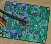
Your DAC sounds very good, even the first listen without burn in or component tweak, or JG buffer. Thank you.
I use LP2985 3.6V reg + 150nF COG noise cap + 22uF X7R output cap (ESR is minimum allowed). There is 470uF BC038 + ferrite + 10uF Silmic II on input. Power is linear from uA7805. I2S source is isolated.
For J1 I use 15R thin film + 470uF Nichicon PLF for RC filter. I use 2x LP5907 3.3V reg with 1uF X7R output cap and 47uF oscon input caps.
XO is TXC 49Mhz with <1ps. It is not the great part but it is the best I can get from the local seller. I fit one flip flop so there is 24.576Mhz output. I will try with CS8421 asrc.
The extra long pads are great. I can parallel 100nF COG with 2.2uF X7R for charge pump. I use 100nF COG + 1uF film for neg rail.
Again, thank you.
Attachments
Good that you like it
I like your setup and that you use the new TI LP5907 Regs. I ordered some and will try them soon too.
Just to make sure: from the picture it looks like you put some Cs (Pana PPS) to R41 and R51?
BTW: stuffed boards (quite good components, matched FETs) will probably be available soon for those who don't like SMD soldering or as basis for further tuning
Best regards, Daniel
Last edited:
Hi,
Yes, you see the R41/R51 is 4.7nF pps, ready to try a second order filter. Today I already tried some different output filter because I cannot buy the coils. I like 4.7nF on the DAC output, 100R for R141/R151, and 9.4nF for R41/51 (it is 2x 4.7nF on each channel). I also try the CS8421 upsample to 96khz and 192khz - the DAC likes 192Khz ! So now I am very happy, especially my soldering on the tiny flip flop is successful, and must listen to more music and more music.
Thanks !
Very glad to hear you're taking your design to a product level Daniel. You've done good work here!
Good that you like it
I like your setup and that you use the new TI LP5907 Regs. I ordered some and will try them soon too.
Just to make sure: from the picture it looks like you put some Cs (Pana PPS) to R41 and R51?
BTW: stuffed boards (quite good components, matched FETs) will probably be available soon for those who don't like SMD soldering or as basis for further tuning
Best regards, Daniel
Thank you
Basically I only put things together with the help of some very experienced people.
Actually it will not really be a "product" level, since then I would have to change the design. When I made the boards I did not have a series production in mind and the components where chosen simply by performance and availability and not price/performance. Also for a product you wouldn't want to match parts.
However I found a partner (or he found me) and some boards will be produced. I am always happy when nice projects are available for the diy community and this way I can contribute a bit
Basically I only put things together with the help of some very experienced people.
Actually it will not really be a "product" level, since then I would have to change the design. When I made the boards I did not have a series production in mind and the components where chosen simply by performance and availability and not price/performance. Also for a product you wouldn't want to match parts.
However I found a partner (or he found me
) and some boards will be produced. I am always happy when nice projects are available for the diy community and this way I can contribute a bit Board dimensions
gmant123: please give me one or two more weeks. Then I will be able to give you more info about availability and price of stuffed boards.
Mull3t: please find attached the dimensions of the board (v1.1, but v1.08 is identical). Measures are rounded to 1/10th mm.
Best regards, Daniel
gmant123: please give me one or two more weeks. Then I will be able to give you more info about availability and price of stuffed boards.
Mull3t: please find attached the dimensions of the board (v1.1, but v1.08 is identical). Measures are rounded to 1/10th mm.
Best regards, Daniel
Attachments
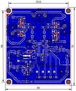
changes from 1.08 to 1.1
There are no significant changes from 1.08 to 1.1.
I moved R8 at Vreg to the top layer which makes the board easier to produce (all relevant* parts on top layer) and did some minor changes/corrections to the silkscreen, e.g. C23, C36 and C38 and +/-15V in connector. So not really worth upgrading existing boards
*BTW: After discussion with Joachim I removed the Rs parallel to the inductors. We both had the feeling it sounds better without. Should still be no problem to solder them between the inductor pins though
Update
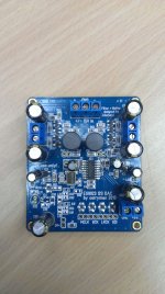
After some minor issues with the manufacturing we are on a good way to release the stuffed boards. Please find attached a picture of a prototype. Please note that some parts have changed for the final version (some Cs).
As you can see the 1:4 MCLK divider parts are not placed to keep the cost down (most users won't use this feature anyway) but pins and traces are still available so everyone can upgrade
We didn't decide on the final price but I estimate something arround 40-45 US$.
I'll announce the boards in the commercial area when they are available
best regards, Daniel
Attachments
You could use the BiB. You'd need three boards... 2x possitive, 1 negative board. +15v -15v for the buffer and +5v for the DAC supply. I'm using 3 Sigma25 supplies from AMB audio. They're a tad bit cheaper than the BiB, and have way less heat. The downside is they probably have a bit more noise than a BiB. They also use standard regulators.
For my next project, I'm going to use the BiB with maybe an i2s based Subbu 9023... if it ever comes to fruition.
For my next project, I'm going to use the BiB with maybe an i2s based Subbu 9023... if it ever comes to fruition.
Search the _Bay for
Transistor Tester Capacitor ESR Inductance Resistor Meter
usually under $20 USD you want the one with the square LSI not rectangular [on the bottom board]. Note the SOT23 pads lower left. Drop the FET on the pads, then hold down hard with tweezers, hit button and wait. Tester will hold the reading a while then shut down.
Thanks for the tip. However, there are several versions of these transistor testers, all with an AVR or similar microcontroller and a 2-line LCD panel, varying from approximately USD 12 to over USD 50 (the more expensive ones have cabinets, more test sockets or a ZIF socket, etc.). Some have microcontrollers in rectangular DIP packages, while others have a square microcontroller.
Most claim to measure MOSFETs, but which one(s) specifically can also measure SOT23 depletion-mode n-JFETs? Many of the cheaper ones have the SOT23 pads at bottom left, but the fine print doesn't claim to measure Idss or Vp of JFETs, though some claim to be able to determine the pinout (which is superfluous for SOT23 JFETs anyway).

@Sergelisses: The key point is not the buffer itself but the improved output filter together with the buffer. The filter is a LCR filter design and improves the suppression of HF noise (compared to the 1st order lowpass normally used with the ES9023 DAC) from the DAC while maintaining a good transient response. It is followed by a JFET Buffer with low distortion and quite good drive capability.
The output filter + buffer has been discussed here in detail and there was a group buy for a filter buffer board designed by EUVL.
I have integrated this design into my own boards and also provided one board to Joachim Gerhard, who is the developer of the filter + buffer and he really liked it like many other do too
@Boomer2: I am also using Salas BIB to power the boards, which works really good. However I also have a version with a slightly improved LM317/337 circuit and it works really good too. The digital section has its own local low noise regs anyway and the buffer has a quite good PSRR. Joachim is using a Traco SMPS (e.g. TMP 15515C) plus CLC-Filter and is quite impressed. I gonna test this too for sure. The latter should be quite simple to realize
Last edited:
I also have a version with a slightly improved LM317/337 circuit and it works really good tooDo you have any info on that reg?
- Status
- This old topic is closed. If you want to reopen this topic, contact a moderator using the "Report Post" button.
- Home
- Source & Line
- Digital Line Level
- Build thread for ES9023 + JG Buffer boards (betatest)