Hi curryman,
I have a question about the connection of my 3 DAC boards with my exau2i. Wiring my setup is a mess with all the cables I would like to know if I could wire it this way:
Is that ok or not recommended? Can I also do it the same with the 5V and +/-15v?
Alexandre
I have a question about the connection of my 3 DAC boards with my exau2i. Wiring my setup is a mess with all the cables I would like to know if I could wire it this way:
An externally hosted image should be here but it was not working when we last tested it.
Is that ok or not recommended? Can I also do it the same with the 5V and +/-15v?
Alexandre
Hi Curryman,
Sorry because this not the right place for these questions, but don't want to use your pm for that.
May you please tell me if the I2S curryman sold by MiniDSP is parts to parts (values, caps type) and pcb accurate in relation to your last (best?) development ?
Is there an still open groupbuy for JG buffers or a link to make it by oneself (pcb plan+BOM) ?
best regards
The boards sold by miniDSP are actually a slightly improved variant of my latest version (1.1 vs 1.08). The parts used by miniDSP are identical to my latest implementation (Pana FR Elcaps, Fox HC73 low jitter XO,...) except the output filter C's which are high quality COG/NPO ceramic caps and not Panasonic PPS film C's.
Regarding the JG Filter + Buffer PCBs you should contact those who did the group buy (EUVL). Maybe they have some left.
regards, Daniel
Regarding the JG Filter + Buffer PCBs you should contact those who did the group buy (EUVL). Maybe they have some left.
regards, Daniel
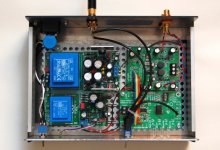
Although I was among the first beta-testers of the DAC board, it took some time to finish the whole thing including cabinet etc.
Now finally some pictures...
I used the curryman PSUs and TwistedPear SPDIF receiver board. With the input selector I could upgrade my CD player and streaming client at the same time.
Philipp
Now finally some pictures...
I used the curryman PSUs and TwistedPear SPDIF receiver board. With the input selector I could upgrade my CD player and streaming client at the same time.
Philipp
Attachments
Although I was among the first beta-testers of the DAC board, it took some time to finish the whole thing including cabinet etc.
Now finally some pictures...
I used the curryman PSUs and TwistedPear SPDIF receiver board. With the input selector I could upgrade my CD player and streaming client at the same time.
Philipp
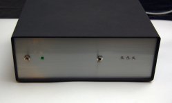
Looks good!
Only the mechanical SPdif input switch seems a bit troublesome to me. Some folks calculate the track width to match 75 Ohm, this is at the other end of the scale
") Doesn't the WM8804 offer multiple SPdif inputs? (for optical / coax)
Doesn't the WM8804 offer multiple SPdif inputs? (for optical / coax)Some screening plates in between the power supplies and the DAC / SPdif board could also help.
For the I2S flatcable, it will help if you take a ground line in between each signal line. This lowers cross-play and gives each signal "sort-of" its own ground.
Thanks.
I discussed the switching issue with curryman before and decided to give it a try.
The cables are 75 Ohm and the tiny switch is expected not to change the impedance very much (screen is also switched). Anyway SPDIF seems to be quite robust regarding the line parameters.
I discussed the switching issue with curryman before and decided to give it a try.
The cables are 75 Ohm and the tiny switch is expected not to change the impedance very much (screen is also switched). Anyway SPDIF seems to be quite robust regarding the line parameters.
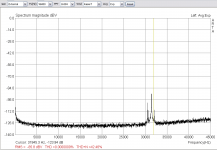
Can someone to feedback us, if there are some peak noise btw 30-35KHz?
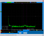
I have attached an ARTA capture about this and an oscilloscope FFT (8bit) capture.
If you set the probe trip (without gnd clip on probe) on the ESS9023 at the upper part of dac-chip (btw pins 6-11), you can see in the oscilloscope display the peaks.
I have attached an ARTA capture about this and an oscilloscope FFT (8bit) capture.
If you set the probe trip (without gnd clip on probe) on the ESS9023 at the upper part of dac-chip (btw pins 6-11), you can see in the oscilloscope display the peaks.
Attachments
Last edited:
Hi Daniel,
Yes the ARTA measurement (noise floor spectrum) is the output of the DAC without input signal. The same happens either direct output or buffer output.
I have a suspicious that this is an internal dac-chip problem because I have double THD to the right channel vs left.
With "without GND clip on probe" I meant the measurement with only the tip of probe (without the gnd clip) on touching the case. As closer to case as better the capture. At the following picture seems what I say...
With "without GND clip on probe" I meant the measurement with only the tip of probe (without the gnd clip) on touching the case. As closer to case as better the capture. At the following picture seems what I say...
Why do you measure with a floating ground? If you do not know the reference, the output is unknown as well.
The ES9023 has an internal inverter (to generate negative voltage), the noise you see can be a lower harmonic of the switching frequency of the inverter.
lemon,
I also measured different THD right vs. left output channel (right is a bit higher though not doubled), however this is mainly due to different 2nd and 3rd harmonic. Can't remember that I measured that noise peak arround 30-35kHz but I will check.
This indeed seems to be a "problem" of the ES9023 since I could measure this in several different implementations (curryman DAC, Subbu DAC v3, ES9023 on SOIC to DIP adapter).
I agree with Hobbit13 that it doesn't make that much sense to measure with floating ground
kind regards, Daniel
First I had seen the result from the ARTA and I observed the range of noise that we talking about.
I was thinking to find if there is area on dac that the fft has the same pattern of noise on this frequencies.
I see that if I have the probe tip over the dac-chip (near pins 6-11) the FFT lifts the same frequency region like ARTA...near to pin 1 there isn't this noise pattern.
The noise is out of acoustic range but it was strange to me! I haven't the appopriate technical documentation for the internal of 9023.
I have measure and another ESS9023 based dac and the right channel had more THD vs left, but was little. At the left channel mine is 0.0029 at the right channel 0.0058.
Daniel, I ''ll be so glad if you can check it to another dac-chip.
Thanks Daniel for the feedback.
Unfortunately, it isn't measurement wrong because this behaviour there isn't to others dacs. As I supposed before, probably I have an unique "dac-chip". I am thinking to change it with a new one, to see...
If you need an ES9023 please let me know. I could send you one.
BTW: What is the manufacturing date code of your ES9023?
regards, Daniel
- Status
- This old topic is closed. If you want to reopen this topic, contact a moderator using the "Report Post" button.
- Home
- Source & Line
- Digital Line Level
- Build thread for ES9023 + JG Buffer boards (betatest)