Well, I had to take a closer look on this too...")
Galaxy Note 2 is equipped with an good DAC processor chip. It should have a very good quality audio out. It have actually when is to compare with other phones out there.
So, my though it were to buy a good headphone set too, to get the most of this phone as audio player. A middle class price Sennheiser IE80 were my choice.
I were disappointed soon enough about the cable of those (else very good quality headphones). The (very good mechanical point of view) cable have an 200pF capacity. There is its compact construction which leads to this huge internal capacity for an 120cm length. To be compared with, an conventional shielded RCA connection cable of 5 - 7 m can reach such capacity. I`ve made my own using silver wires (quite nice result), 60pF total capacity including its connectors. Good sound! I use Neutron as music player.
But it were not just enough for me. I decided to take a closer look at how the hardware is made in to the phone itself. I used an YouTube video (Galaxy Note 2 - N7100 Complete Disassembly & Assembly) to learn how to tear down this phone.
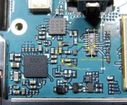
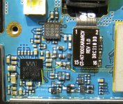
So, I found out what is pictured here out. The meaning of this mod is to remove the 150pF caps which are to ground the signal for filtering reasons in high frequency domain. I have to say that this is very difficult mod. The components looks quite big in the picture, but in real they are very small. Without good skills and very good soldering tools, one may not even think to try this...
The final result (and the first listening impression) it were not spectacular, but a little bit better sound stage i could hear. After more listening the improvement become more noticeable: the sound is better defined, and the details are more evident. An increasing in dynamic is also noticeable. The few distortions in some high special music passages are not noticeable now, as before. At least I`m satisfied with the overall result so far. I can even say that I`m glad I could get this improvement for my portable music player...
I`m not very sure if the improvement can be noticeable using an low end headphone, or even with those Sennheiser IE80 with the original 200pF capacity cable... To say, 200pF capacity for the cable + 300pF those caps on the DAC output, it become an quite important capacity on the outputted signal. I personally did not liked that... BTW, I may say now that the elements inside those Sennheiser IE80 are just exceptional. The bass is really impressive and the details in highs are very well reproduced. I have to admit that I worked a little bit around on those elements of Sennheiser IE80 too (only a little bit... )
The 150pF caps it were measured after desoldering process. The right value of those it may be altered by the heating. I do not know the real value Samsug used in this device. I have to precise a little more about the components used on all the outputs which are to use long wires connected (marked with C on it). It seems also to be a protection to the accidental high electrostatic levels which it may be developed on those long wires connected to the phone (headphones, audio cables, etc). Those components are placed on all the output/input used in this stage (DAC out, radio antenna, mic, etc). It may not be in conduction in normal functioning mode, so I think it will not negatively affect the audio signal out. I`m convinced now that the 150pF caps did influence in negative way the outputted audio signal.
It could be nice if somebody else will find something more about this DAC circuit and its around components... I will like to know the components used on the power rails of the DAC. The 0550 DQKN chip is the radio receiver.
On the bottom/center of the pictures it is an quite large circuit, where the components it seems to not be in use as how are connected. It looks like something power regulators, but important connections are not made on this phone model...
It is possible that a part of the sound improvement with this mod in place it may also come from the upper shielding of the DAC chip, but I can not be very sure about this and how much it may be the procent... Is not very easy to experiment with a device which is quite difficult to be disassembled, and the risks to destroy it`s plastic pieces is enough high.
Galaxy Note 2 is equipped with an good DAC processor chip. It should have a very good quality audio out. It have actually when is to compare with other phones out there.
So, my though it were to buy a good headphone set too, to get the most of this phone as audio player. A middle class price Sennheiser IE80 were my choice.
I were disappointed soon enough about the cable of those (else very good quality headphones). The (very good mechanical point of view) cable have an 200pF capacity. There is its compact construction which leads to this huge internal capacity for an 120cm length. To be compared with, an conventional shielded RCA connection cable of 5 - 7 m can reach such capacity. I`ve made my own using silver wires (quite nice result), 60pF total capacity including its connectors. Good sound! I use Neutron as music player.
But it were not just enough for me. I decided to take a closer look at how the hardware is made in to the phone itself. I used an YouTube video (Galaxy Note 2 - N7100 Complete Disassembly & Assembly) to learn how to tear down this phone.
So, I found out what is pictured here out. The meaning of this mod is to remove the 150pF caps which are to ground the signal for filtering reasons in high frequency domain. I have to say that this is very difficult mod. The components looks quite big in the picture, but in real they are very small. Without good skills and very good soldering tools, one may not even think to try this...
The final result (and the first listening impression) it were not spectacular, but a little bit better sound stage i could hear. After more listening the improvement become more noticeable: the sound is better defined, and the details are more evident. An increasing in dynamic is also noticeable. The few distortions in some high special music passages are not noticeable now, as before. At least I`m satisfied with the overall result so far. I can even say that I`m glad I could get this improvement for my portable music player...
I`m not very sure if the improvement can be noticeable using an low end headphone, or even with those Sennheiser IE80 with the original 200pF capacity cable... To say, 200pF capacity for the cable + 300pF those caps on the DAC output, it become an quite important capacity on the outputted signal. I personally did not liked that... BTW, I may say now that the elements inside those Sennheiser IE80 are just exceptional. The bass is really impressive and the details in highs are very well reproduced. I have to admit that I worked a little bit around on those elements of Sennheiser IE80 too (only a little bit...
) The 150pF caps it were measured after desoldering process. The right value of those it may be altered by the heating. I do not know the real value Samsug used in this device. I have to precise a little more about the components used on all the outputs which are to use long wires connected (marked with C on it). It seems also to be a protection to the accidental high electrostatic levels which it may be developed on those long wires connected to the phone (headphones, audio cables, etc). Those components are placed on all the output/input used in this stage (DAC out, radio antenna, mic, etc). It may not be in conduction in normal functioning mode, so I think it will not negatively affect the audio signal out. I`m convinced now that the 150pF caps did influence in negative way the outputted audio signal.
It could be nice if somebody else will find something more about this DAC circuit and its around components... I will like to know the components used on the power rails of the DAC. The 0550 DQKN chip is the radio receiver.
On the bottom/center of the pictures it is an quite large circuit, where the components it seems to not be in use as how are connected. It looks like something power regulators, but important connections are not made on this phone model...
It is possible that a part of the sound improvement with this mod in place it may also come from the upper shielding of the DAC chip, but I can not be very sure about this and how much it may be the procent... Is not very easy to experiment with a device which is quite difficult to be disassembled, and the risks to destroy it`s plastic pieces is enough high.
Attachments
Last edited:
You follow me everywhere...
I`m impressed about your attention... Anyway you are free to comment of course
If you were sarcastic in your comment, then may I say that in this case is about filtering caps placed on the audio output of that DAC chip, on the audio signal path. Is not so important to filter out WiFi frequencies or something else when one use headphones to output the audio signal... When about amplify this signal further it may be in one way important, but anyway it is about so high frequencies, which it may be attenuated anyway... Will not be amplified of an power audio amplifier... About this we discussed before, but it seems to me that you do not agree to this... Anyway...
In this case is more important to get the most of that DAC chip. This is a possible way to do it. Have you another better way(s), then you are welcome. But it seems to me that you were not so interested in this field, so it were somebody else who did it before you...
Last edited:
Hi Coris, nice trick, have you tried it with an external Dac yet?
I want to build a dock for mine incorporating a minidsp and optical input from my pc. I had been thinking of using a DAC5 or maybe this dac,
eBay Australia: Buy new & used fashion, electronics & home d?r
I want to build a dock for mine incorporating a minidsp and optical input from my pc. I had been thinking of using a DAC5 or maybe this dac,
eBay Australia: Buy new & used fashion, electronics & home d?r
not following you, again same old same old, if you cannot hear a problem, it must not be happening.... you HAVE made things worse, that is not a matter of opinion. somebody has to inject a bit of perspective/reality to counter your fantastic assertions. I know you willfully create conditions for error, or simply dont understand the fundamental operation of circuits. it seems to be the basis for many of your mods, so I post for others, not for you; so that they may avoid damage to their equipment (either directly through lifting a trace or static discharge) for no reason whatsoever.
you expect to hear directly a problem even though we are talking MHz? its a completely pointless mod, it has only possible negatives. The filter shunts VHF to ground at the output from a device that transmits and receives signals in the VHF on the same PCB and air around it. thats the filters only purpose and thats its only effect, it only provides a low impedance to ground for VHF, the capacitor cannot pass anything else, it cannot effect audio frequencies, so you only open the door for letting stray RF into the audio. there is absolutely no scope for improvements for audio frequencies. The only thing you do by removing them is close off this way out for the VHF, so it stays in the signal
but I forgot, you have these awesome ears that hear only improvements
Last edited:
Hi Coris, nice trick, have you tried it with an external Dac yet?
I want to build a dock for mine incorporating a minidsp and optical input from my pc. I had been thinking of using a DAC5 or maybe this dac,
eBay Australia: Buy new & used fashion, electronics & home d?r
Hi Beau
I did not tried yet so. Basicly I do not like the idea to put together two or many boxes and take with me those everywhere with the phone (as a music player). Of course it may be a substantial improvement to connect a (USB) DAC to the phone in a docking station. But then it may be not so "mobile" all the system anymore...
As a stationary device I would prefer another (better) ways. A phone by itself is not just the best device to play music with. But I`m pretty satisfied with the technology/quality of the audio stage in Note2. It may be even better in the quite soon expected Note 3...
I would like to precise here that I do not encourage somebody else to modify their phone devices. If one may want to try it will of course be on it`s own risk.
From my part, I found out about something in this direction and I thought to share it with that community eventual interest in the same subject.
Thanks to qusp for his good intentions in the above interventions: he desperately try to save the world from the "bad" guy! This is very nice!
You are a real DIY Audio Superman (Super-member). Congratulation!
At last an friendly advice to you: do not get so stressed/upset about my posts/findings/mods. Is not so healthy...
This is very nice!You are a real DIY Audio Superman (Super-member).
Congratulation!At last an friendly advice to you: do not get so stressed/upset about my posts/findings/mods. Is not so healthy...
Last edited:
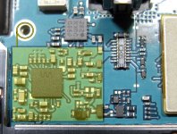
About the mod above, I forgot to mention an detail more: I applied finally an HF shield over the DAC area chip as is to be seen in the picture here. Connected to GND as is showed in the picture too. There is enough place there to such.
(I forgot to take a picture of the final "look", and I do not want to open the phone again to do that...)
(I forgot to take a picture of the final "look", and I do not want to open the phone again to do that...)
Attachments
Wouldn't trying to create a circuit diagram, using the board and the DAC data sheet be prudent, then you will know what you are altering and not just randomly replacing components. If you are going to shield I would suggest Henry Ott, placing a co9nductive shhet over the conmponents will not achieve anything, why are RF cans soldered to the board with NO gaps.
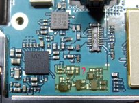
There is not about her randomly replacing of components. Before take out that filtering caps I measured (of course) and identified the channels and the components as it shows in the pictures. There is an pi filter there on output, made of those two 150pF caps and the ferrite bead in between, then the "varistor" at the end of that filter.
I have appreciated that it may be better result without the 300pF capacity on the signal path. My appreciation it were confirmed by the better quality of the outputted sound.
So, it is not just randomly all about here...
I have used to shield the DAC area, an material special made for HF shielding purposes (quite advanced material I may say).
To make a diagram of that circuit area is quite impossible because the lack of important informations...
Hi Coris,
I've always loved pulling things apart and looking inside, making changes, see what happens... but you know ppl here don't respect that. I do. Go for it - but not with my phone !
Do you think you can hack spdif from this thing ? It might a fun thing to be able to use the headphone jack for spdif out ?
EMI shielding is all about seams and slots.
If there is a pi filter there it is there for a reason, if one was reverse engineering a product for whatever reason it is best to try an map out a schematic first. It nothing to do with respecting this that or the other it just a more refined and controlled way of doing such things...
Also these days especially on consumer goods there is always a very good reason why components are there, just on the basis of cost factors.
I agree with you: yes, there is a reason things are in place as it are.
There was a designer or many who thought in one way, and they found that it may be in that way (for that reasons...), based on a task list. Maybe someone else find that some of that reasons few people have done it so, are not worth for another particularly reasons, one may use that device, or functions/fractions of it. So, what is wrong in this? The reasons are changed, the mod is in place, the functionality is improved (for that particularly reasons), everything works well, and everybody is happy (except one or few DIY members who do not want to accept such way...).
The pi filter in this case is placed on the output of the DAC stereo lines. For sure I may not even think (without having very detailed informations) to remove such filtering caps from an filter placed in RF domain, or so.
I may admit that I took a risk to remove those caps without enough reverse engineering or detailed analysis of the (completely unknown) circuit. The reverse of this action it could be a wrong functioning in some stages. It were not. So we are now a step forward: it works! No damages! BTW, even the sound from the radio receiver in my phone is now more detailed...
At least such way to do it things may very well be called "half controlled". A kind of shortcut...
I let the long way to others... who are very welcome here to show us in fact the "right" way.
From my part, I showed the result of an shortcut...
Last edited:
Hi Coris,
I've always loved pulling things apart and looking inside, making changes, see what happens... but you know ppl here don't respect that. I do. Go for it - but not with my phone !
Do you think you can hack spdif from this thing ? It might a fun thing to be able to use the headphone jack for spdif out ?
I do not think this is possible (SPDIF). At least it is not necessary at all. The necessary digital signals for sound are routed to the USB port by particularly applications. There are on marked USB devices which can take the digital signals from USB port of the phone and process it in a more performant DAC (portable) system (with better sound). But then one may carry on two boxes to play music (phone + DAC). I do not like at all this solution. It works much better to have a stationary DAC system at home...
Last edited:
there is no right way to remove a perfectly good RF SHUNT filter from a headphone amp/dac output which has onboard wifi/telephony transceiver. common mode and differential filters are a bit of a black art when you know what you are doing...
here you go again throwing the word fact around willy nilly. so you have changed the filters response from ? to ?
no thats correct KK, I dont respect removal of integral and correct design and declaring an improvement in 'detail' from the appearance of MHz signals. there is only one explanation here for that... I wont say it out loud.
Coris has been playing with things for many years now, one would hope a more procedural approach and respect for the functionality of things might be evident by now... nothing wrong with experimentation, but even experimentation should have some sort of aim and some sort of effort to see if its been reached. sorry listening for the appearance or disappearance of RF signals is not a valid testing regime... the headphones only reproduce up to maybe 20khz...
the transport/DAC/Amp/headphone circuit has no means to create legitimate signals at these frequencies the filter conducts, the ONLY thing that can appear is noise
Last edited:
- Status
- This old topic is closed. If you want to reopen this topic, contact a moderator using the "Report Post" button.
- Home
- Source & Line
- Digital Line Level
- Galaxy Note 2 - audio stage mods, discussions, improvements ideas