wow where does a 5 yr luker start..
I usually figure stuff out myself by reading on here. great site
HOWEVER>> every attempt to solve my problem has turned up a blank or no reply( yahoo groups, search here, audio circle, etc)
Simply, I have a full kitted DCX2496 ( i.o board, clock, regs) supplied and assembled by Pilgham Audio .
OK it doesn't work!!!! well.
Specifically the ANALOG INPUTS do not function correctly, with any preamp I have, or at least any preamp or input source with a 3-wire plug.
CONNECTION>
PREAMPS TO DCX via RCA to XLR cable..pin2 +/center pin3 -/gnd using mogami 2534 cable
ok hook the tuner to the PREAMP and the PREAMP to the DCX.. and the DCX craps out.. tons of channel crosstalk and the balance control(preamp) goes to crap
in other words the balance doesn't even work..all that happens is the levels get lower in both channels at the DCX input!! you can see this on the input meters on the dcx, along with listening to the output.
switch to balanced connections even worse.
ok remove either channel of the input from the PREAMP to the DCX .. hmm no crosstalk.. and the balance control works now!!
IE turn to the disconnected channel, no sound, no input level lights, turn to the connected channel ...sound and input lights at proper level
secondly How the HECK when I check from pin 2 input to Pin 1 OUTPUT do I get dead short?? WTF? I know he uses some weird circuit R to convert unbalanced to balanced on the output but??? no way the pin1 output ground should show a short to the input hot pin!!
I can't get a schematic of the DIDDEN i/o board and really have no clue to where to start trouble shooting
other than BOTH preamps work perfectly with all my other gear/ amps/ crosovers, etc. and signals look good on scope and no huge amounts of dc( 20 ma max.)
Please help before I throw this $1000 POS in the garbage!
Last edited:
Well, it's DIY so time to jump in there and figure it out. Sux that you have to undo what someone did, but maybe it's a simple fix. Often is.
The digital input is working OK? If so, sounds like the problem is just the interface the the ADC chip.
Do you have good pics of the mods?
The digital input is working OK? If so, sounds like the problem is just the interface the the ADC chip.
Do you have good pics of the mods?
ya it major kungfu sux.. but
I've scanned all the forums and found nothing ,,.I assume most people don't use the analog input
but ... this is on the DIDDEN Rev 2 i/o board.. so its not in the analog to adc unless its screwed up on his board.. and agian why is the pin 2 input hot! showing a short to the output gnd(pin1) the output has to go thru a opamp(s) i mean this circuit is really screwy!
Did you email Jan Didden?
Sounds like something was just wired wrong during the build. Or it could be your cables.
Who performed the mods?
Are both channels wired identically? Does only one channel have the hot-to-otuput-ground short?
Have you removed the board(s), to check for shorts/solder bridges?
If there are two channels that should be identical, you could measure (with unit unplugged) resistance to chassis at corresponding points in both channels and look for differences.
Do you know of anyone else who has one that should be identical, to compare photos?
Is the schematic available at a link anywhere?
Do you have photos of the input connections?
Last edited:
yes...
probably but the board has been back to ward ( twice)" worked fine in my dcx"
not that i can find if so i could locate the problem
I can take some but they are posted all over the forum .. what specifically are you looking for>??
its just 2 wires from pins 2/3 to his board.
let me know I can post some
OOPS missed half your post
Did you email Jan Didden? yes
Sounds like something was just wired wrong during the build. Or it could be your cables. not cables.. works fine on all my other assoc gear see above.. even substituted different cables.. been checked on scope and ohm meter too
Who performed the mods? Pilgham audio
Are both channels wired identically? Does only one channel have the hot-to-otuput-ground short?yes from my preamps to the dcx no both channels do it.
Have you removed the board(s), to check for shorts/solder bridges? yes
If there are two channels that should be identical, you could measure (with unit unplugged) resistance to chassis at corresponding points in both channels and look for differences. none
input a input b on dcx pin 2 shorts to any output pin 1
Do you know of anyone else who has one that should be identical, to compare photos? ita alin the board.. not a issue of hooking 2 wires per input to pins on his board. his board only had 2 pin for input a+pin 2 a- pin 3 ditto for input b
Is the schematic available at a link anywhere? not that i can find..jan said no schem available!!!!
Do you have photos of the input connections?what 2 wires to the pins?? see last page of pdf.. this is all the info i have
Attachments
Well, the other ends of the wires must go somewhere too?
I loked at the PDF and it seems like there might be a significant potential for errors when constructing and connecting the internal cables. They seem like the most-likely source of error.
You might want to start by making a diagram or table that maps out all of those connections, starting with the ones at the inputs and outputs. i.e. Work from the actual wiring and draw the connections out. Then compare them to what the PDFs says they should be.
I would map them out both visually and with a meter. Pin-header types of connectors are not known to be the most-reliable and trouble-free connectors. And the wires in ribbon cables are sometimes easy to connect in the wrong order, when they are split and soldered by hand.
Last edited:
yes, honestly I find your attitude pretty rude and your seeming unwillingness to even consider the possibility its your error is unlikely to get you far trouble-shooting. you have said nothing of the power supply hookup, posted no pics and jumped straight to obnoxious mode.
Jan is a well liked and well respected long time member here and he does generally know what hes doing, so your posts, which basically insinuate that Jan is lying about it working fine and testing fine at his end, or is an idiot that sells dysfunctional garbage. I think its totally uncalled for...
I can only echo what gootee has said above given the nature of the malfunction, the fact its been back twice and confirmed by a man I consider to be reliable and generous to be functional, the ribbon cables, or your internal hookup/grounding seem the most likely source of error
Last edited:
Let's keep personalities out of this, shall we? If the digital section works, then it can't be the output section. That leaves some miswiring or bad component on the input.
I don't know your mod, but the mods I do to the DCX simply replace the stock opamp input circuit with a new one that is simpler and uses higher quality parts. It's not very difficult and works well. If you can solder, you can make one. To troubleshoot this you'll need to trace the wires. Is that something you can do?
AFAIK, the Didden mod does not include the input. Or am I missing something here?
Unfortunately the OP is not being clear about the specific problems and beating up on Jan is not helping.
As others have pointed out, it is probably a poor connection or something has been mis-wired.
It is also clear that a simple phone call between the OP and Pilgham audio
would probably solve this quickly. My advice: keep the phone call on a friendly and respectful tone.
As others have pointed out, it is probably a poor connection or something has been mis-wired.
It is also clear that a simple phone call between the OP and Pilgham audio
would probably solve this quickly. My advice: keep the phone call on a friendly and respectful tone.
Indeed- the design is solid, it's worked for hundreds of other people. That's not your issue.
The only question is the implementation, and it really would be better to go to Pilgham directly. If you've done further work beyond what Pilgham did, expect to be charged for their time and effort if what you did caused the problem.
The only question is the implementation, and it really would be better to go to Pilgham directly. If you've done further work beyond what Pilgham did, expect to be charged for their time and effort if what you did caused the problem.
Let's keep personalities out of this, shall we?
exactly what I was suggesting, so far the OP joined and proceeded to post in the DCX threads with suggestions of incompetence and impropriety; as well as starting this one, which assumes error to be anywhere but his own and using CAPS and statements that lay the blame squarely on Jan. now it may be a strange error that has somehow been missed, but the way this is being handled is not helping anyone.
there is as much or more chance of user error than someone who has put together many of these and confirmed the module itself to be functional after being returned twice. given what ive seen here in the last couple of days, I wouldnt blame Jan for getting fed up.
it would seem so yes. throw pin 1 as signal ground and SE->BAL conversion with opa1632 and its feedback, possibly unnecessarily complex/fiddly adapters into the mix and you have plenty of room for error/conflict on a system level.If the digital section works, then it can't be the output section. That leaves some miswiring or bad component on the input.
let me explain.
I have over 80 emails and a year and half trying to trouble shoot.. not to mention finding numerous "quality" issues along the way
so excuse me for being short...or having an "attitude" as you put it.
I'll be gald to dump you all my email files! and picutres
it is in the DCX ...again all my other equipment works fine! and no analog input device works correctly.. in the units inputs
this unit was supplied complete by Pilgham and has never worked correctly on the analog inputs..ever..
how does 2 preamps and a tuner input not working constitute a problem on my part?
I'm just trying to fix something that doesnt work properly.. and it's been to Europe twice..
He siad it workd with "HIS"equipment...ie Philgham... not JAN
FY the preamps are coda pre01 and parasound p3.. the dcx does not work correctly with either unit balanced or unblanaced inputs!
so I cant run my phono sections!
maybe there is a "compatibility " problem but without schematics no way to find it..that's why I'm asking for suggestion to look for
still doesn't explain the pin2 input to pin 1 output short!
so explain that first and we will go from there..
also have met several other people with similar problems on yahoo forums..
ie things not working as they should..be glad to post pics.. but I'm trying to avoid draggin jan or ward into this.. since I hav egotten no where in a year and ahlf..
I'd like the dang circuit so I can send to coda and parasound see if we can figure otu and trouble shoot the problem..
doesnt look like that is happening so.. here i am "attitude" and all
I will speak in private with anyone who wants to see picture of Pilghams work!
Last edited:
I have tired, I have begged.. its real simple..I'm sticking to the facts as to what has happened.. If I seem to be slamming jan or ward so be it.. I'm just trying to fix my POS DCX.
when any analog signal is fed into the dcx via a preamp..it goes to crap.. ie if I turn the balance control to the right or left both channels drop!!!! also if I turn the volume up enough to get any input light on the dcx(over 1v) I start getting huge amounts of distortion..
If I UNPLUG one channel then presto I get full signal and that one channel works fine. as I said in itital post.
that lead me to think there is a grounding issue in the input circuit. or somethign shorted ont he board.without schems .. no way for me
jan initially blamed it on dc input.. so I asked how much it too much? 20 ma is what I measure .. no relpy..
I also asked for the specific pin input configuration(ie which of the four pins correspond to the +/- a/b channels) on the rev2 board.. no answer..
only to wire the cables as shown in manual.
when Pilgham sent my unit back they sent back a set of analog connectors and xlrs..
these were wired 180 degrees from my original supplied units.. hence I think my question was a logical one.. esp since neither arrangement works.
jans input circuit is supposed to take bal and unbalanced signal.. it's worse on balanced signals..i dunno..
now I have $950+ usd plus an addition $80 in back and forth shipping and I still dont have a unit that works with my preamps! yea im pissed!
again #1 why does pin 2 input show continuity to pin 1(gnd)OUTPUTS??
Last edited:
yeah sorry this is too hot for me and i'd rather not get involved, I do hope you can sort it out. I dont wish anyone that sort of frustration, regardless of cause or blame. I dont know either unmodded or modded unit to help anyway. I do have some experience with the opa1632 used in the analogue input, but i've not used its unbalanced-Balanced conversion features, only balanced in-out.
I do wonder if VCOM and input grounding conflict for the SE->BAL has something to do with it. are there relays used? any protection circuit?
I do wonder if VCOM and input grounding conflict for the SE->BAL has something to do with it. are there relays used? any protection circuit?
Last edited:
yea I got more time trying to revese engineer this thing than I would have just to build a 4 ways active myself..
really not worth the effort.. and the issues with the dcx make the mods questionable at best..
I needed it for convience /r&D and well better sound out of the dcx..
so far I've had none
really not worth the effort.. and the issues with the dcx make the mods questionable at best..
I needed it for convience /r&D and well better sound out of the dcx..
so far I've had none
never said there was no problem, its a matter of where. but there is almost nothing we can do with no photos, no schematic, no actual measures . so because of that it just came off as a rant
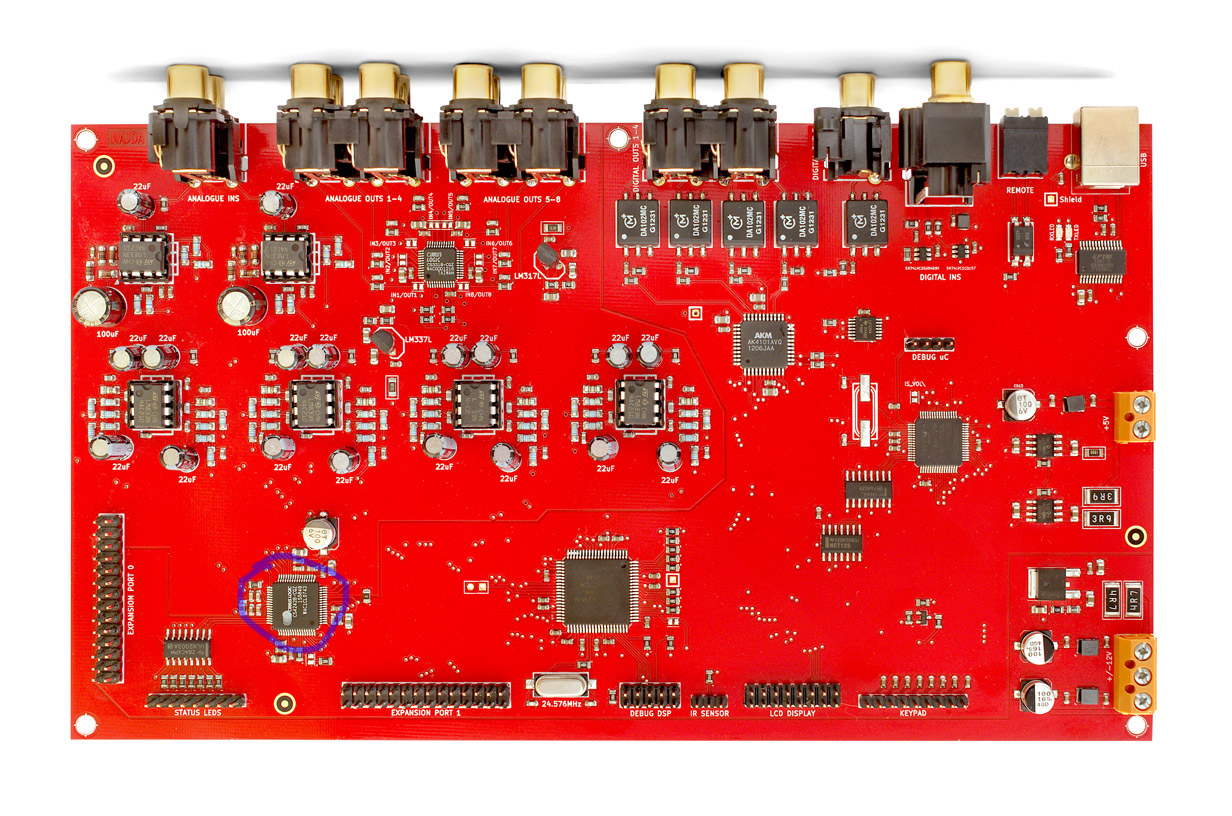
agreed on the DCX though, these days I do feel there are better options. you might look at this Nadja. looks very good, only just about to start shipping soon, so cant give feedback on sound, but software looks good and hardware is much more powerful than dcx. 8 analogue outs or 10 digital outs, optional digitally controlled analogue volume control, or 32bit digital as stock etc etc. pretty interesting.
agreed on the DCX though, these days I do feel there are better options. you might look at this Nadja. looks very good, only just about to start shipping soon, so cant give feedback on sound, but software looks good and hardware is much more powerful than dcx. 8 analogue outs or 10 digital outs, optional digitally controlled analogue volume control, or 32bit digital as stock etc etc. pretty interesting.
Last edited:
- Status
- Not open for further replies.
- Home
- Source & Line
- Digital Line Level
- HUGE ISSUE with DIDDEN DCX mod