So I stole DC power from the CD player PCB and connected it directly to the 7805 on the converter board. There was a big difference. Much flatter reproduction. Still a bit of a problem around 1k and lacking a little detail, but it's getting pretty good now. For the next upgrade I think I'll stick the 12MHz TCXO on a fancy clock board that I'm not using right now. Any other suggestions?
More improvement! Doing some reading on the Internet I discovered that using iTunes may have been part of my problems. This is a very low budget project and I'm using Mac OS 10.4 on an old PowerPC based PowerBook so my options are limited. I found two free players: Vox and Play. Using Vox resulted in a minor upgrade, but Play gives me a very nice sound.
Here are the links to the two free players:
Vox :: The Lightweight Music App for Mac OS X
Play from sbooth.org
I think Vox has the better interface, but I only care about sonic quality right now. Beggars can't be choosers...
I'll still put the TCXO on the clock board soon. I guess I could buy a low jitter clock too. VALab has one on ebay that's not too expensive. What about upgrading the voltage 3.3V regulator to the TE7022 chip?
I'd like to improve the power to the TE7022. Right now I've got about 14VDC from the player PCB going to a 5V regulator on the USB board. A surface mount 3.3V regulator for the TE7022 is connected to the 5V regulator output.
I don't need 5V on the USB board anymore because the TCXO is now on a separate board with its own power. Would it work to simply remove the 5V regulator and then run the 14VDC directly to the input pin of the 3.3V regulator?
I don't need 5V on the USB board anymore because the TCXO is now on a separate board with its own power. Would it work to simply remove the 5V regulator and then run the 14VDC directly to the input pin of the 3.3V regulator?
I also bought this TE7022-based board, and hooked it to the I2S pins of a TDA1541A on a board from an old Philips player. I sent 16/44.1 audio from my PC. It seems the LRCK is 44.1 kHz, but the data is still 24-bits. The analog audio output it too low. Still playing with it...
I also bought this TE7022-based board, and hooked it to the I2S pins of a TDA1541A on a board from an old Philips player. I sent 16/44.1 audio from my PC. It seems the LRCK is 44.1 kHz, but the data is still 24-bits. The analog audio output it too low. Still playing with it...
That is strange. I have a very similar installation and there is lots of gain. I2S output from converter board directly to I2S input of a TDA1541A chip. Did you disconnect the I2S lines coming from the SAA7220?
I also bought this TE7022-based board, and hooked it to the I2S pins of a TDA1541A on a board from an old Philips player. I sent 16/44.1 audio from my PC. It seems the LRCK is 44.1 kHz, but the data is still 24-bits. The analog audio output it too low. Still playing with it...
Also, did you ground the signal? GND (next to SCLK on my converter board) needs to be connected to ground on the CD player PCB.
Yes and yes. When playing back a full scale sine or square wave I get 235 mV peak-to-peak instead of 6 V on both channels. To be honest I never tested this PCB with a transport. The DC level at the output of the I/V opamp is 3 V, so I suppose it works as it should. (Mute is disconnected, analog filter is bypassed).
The eBay seller informed me that the I2S output is 44.1 kHz 16-bit. So probably the coax and optical output (not implemented on my unit) can go up to 96 kHz 24-bit.
Interesting. I wonder then why I wasn't successful in connecting to the I2S input of the YM3414. I thought it was because the signal was coming in 24 bit "words".
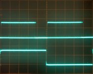
Might there be a problem with my unit? I read the I2S Bus specification from Philips, and it says the WS line changes one clock period before the MSB is transmitted. However on the oscilloscope screenshot above the MSB is transmitted several clock periods after the WS edge. I suppose the receiver TDA1541A expects the MSB according to the I2S spec, but it gets zeros for 3 or 4 clock periods, then it comes the real MSB (let's call it Bit15), which it interprets as Bit12 or Bit11, and the analog signal is attenuated accordingly by 8 or 16.
Might there be a problem with my unit? I read the I2S Bus specification from Philips, and it says the WS line changes one clock period before the MSB is transmitted. However on the oscilloscope screenshot above the MSB is transmitted several clock periods after the WS edge. I suppose the receiver TDA1541A expects the MSB according to the I2S spec, but it gets zeros for 3 or 4 clock periods, then it comes the real MSB (let's call it Bit15), which it interprets as Bit12 or Bit11, and the analog signal is attenuated accordingly by 8 or 16.
Maybe there is a problem with your USB unit? I wish I could give you more ideas but I can see that you are more advanced in electronics that I am. All I can say is that I connected the I2S signal from the converter board directly to the I2S inputs on both a TDA1541 and a TDA1541A with no problems. The only other thing I can think of to make sure the proper mode is selected with pin 27 on the TDA1541A.
Hopefully someone else with more knowledge can join the thread...
I installed the TeraLink-X2 driver, and the USB to I2S converter works properly")
That's great! Are you going to do any modifications to the converter board and/or the CD player board?
So I've gotta bunch of classic Philips CD players, with their internal TDA1541A, TDA1545A and TDA1543 DAC beggin' to return to their glory days...
...and along comes a POTENTIAL $23.00 USD solution from HK/China's nutsaudio.com ...

SPECS:
24/96 USB > SPDIF + ANALOG TE7022 + I2S CONVERTER for DAC
ALREADY ASSEMBLED
Input voltage : AC 9V or DC 8~13V or by USB
PCB Size : 80mm x 40mm
D/A chip: N/A
USB : Chip : TE7022L
Digital inputs: 1 X USB
Outputs: ANALOG - not available , DIGITAL - RCA + I2S
Methinks this is the same board posted way back on page 1 of this thread ... IAC... what do you folks think?Are they really nuts ... or might sticking the board above into a Philips CD-650 be an interesting experiment? Anyone tried this (or similar board, breadboard DIY or China kit)?
...and along comes a POTENTIAL $23.00 USD solution from HK/China's nutsaudio.com ...
SPECS:
24/96 USB > SPDIF + ANALOG TE7022 + I2S CONVERTER for DAC
ALREADY ASSEMBLED
Input voltage : AC 9V or DC 8~13V or by USB
PCB Size : 80mm x 40mm
D/A chip: N/A
USB : Chip : TE7022L
Digital inputs: 1 X USB
Outputs: ANALOG - not available , DIGITAL - RCA + I2S
Methinks this is the same board posted way back on page 1 of this thread ... IAC... what do you folks think?Are they really nuts ... or might sticking the board above into a Philips CD-650 be an interesting experiment? Anyone tried this (or similar board, breadboard DIY or China kit)?
Last edited:
- Status
- This old topic is closed. If you want to reopen this topic, contact a moderator using the "Report Post" button.
- Home
- Source & Line
- Digital Line Level
- Hacked TDA1541 CD Player USB DAC Idea