So I've got this idea to use a USB to I2S board something like this http://www.ebay.ca/itm/110906343285?ssPageName=STRK:MEWAX:IT&_trksid=p3984.m1423.l2649 and patch it in to pins 1,2, and 3 of the TDA1541A chip on my old CD player, completely abandoning the actual CD playing function and eliminating any oversampling/filtering (ie. SAA7220).
Would this work? If so, would I need any attenuation or buffering between the USB/I2S board and the TDA1541A chip?
Would this work? If so, would I need any attenuation or buffering between the USB/I2S board and the TDA1541A chip?
So I've got this idea to use a USB to I2S board something like this http://www.ebay.ca/itm/110906343285?ssPageName=STRK:MEWAX:IT&_trksid=p3984.m1423.l2649 and patch it in to pins 1,2, and 3 of the TDA1541A chip on my old CD player, completely abandoning the actual CD playing function and eliminating any oversampling/filtering (ie. SAA7220).
Would this work? If so, would I need any attenuation or buffering between the USB/I2S board and the TDA1541A chip?
Board have I2S out, and this should work with TDA1541A.
It will be better option, to carefully take out TDA1541A from CD board without damaging chip/board, and make new DAC board based on Pedja Rogic DAC. Also, if 16/44.1 is enough, PCM2707 can be used for DIY PC USB/I2S bridge.
Thanks for your response! I am trying to do with this with very little money so I don't think I can afford to make a new DAC board. Plus, I am having difficulty finding a schematic of Pedja Rogic's design. He now sells complete DACs and doesn't sell DIY parts or kits.
I am curious about why you recommended the PCM2707. I thought I read that it can have jitter issues, but maybe I'm wrong?
I am curious about why you recommended the PCM2707. I thought I read that it can have jitter issues, but maybe I'm wrong?
If you use as short a cable as possible then you shouldn't need any buffering / attentuators. However using a cat5 cable with one of each pair grounded at both ends helps as I understand it.
Your idea will work though, I've done exactly that myself.
There are better solutions than the 2707 like the one you linked but the 2706/2707 is easy to diy (especially if you can make your own pcb's) and they're cheap - I think you can still get free 'samples' if you know where to look(!). One option is this - just leave out all the coax/optical bits and you've got an easy to make (and cheap) usb to i2s converter.
Thanks; that's more food for thought. Speaking of the 2707, this looks like a really nice USB kit: http://www.dddac.de/pics/dddac1543mk2/usb-receiver32-003.jpg (receiver chip soldered on the underside) but at 39 Euros plus 29 for XO clock plus shipping it's getting a bit pricey...
Last edited:
For that money your first link would make more sense I think - or even something based on a CM6631. These would give you more options for trying different DACs in the future as well.
Adding low jitter / high quality clocks to the 2706/07 has always puzzled me a bit as that chip reclocks internally so I'm not sure how much of an impact the quality of the external clock makes - plenty of kit makers do it though so they probably know something I don't!
In my humble opinion the 2706/07 only really makes sense if you're scratch building these days, it is smd but I've managed to solder a couple of them using a standard iron, they're pretty robust.
I wasted a bunch of time studying the datasheet and can't help but draw the same conclusion, since it recovers the clock from the incoming data. Maybe an upgraded clock makes that recovery process less prone to errors? Nevertheless the manufacturer recommends against adding an external clock anyway...
I forgot to mention that I also need compatibility with MacOS 10.4. TI officially confirms this for the 2706/7, which is nice.
I forgot to mention that I also need compatibility with MacOS 10.4. TI officially confirms this for the 2706/7, which is nice.
So I ended up buying the TE7022 board.
I hooked up the I2S signal to the I2S input of my TDA1541A CD player's filter chip (which happens to be a Yamaha YM3414 instead of the usual SAA7220).
The audio comes through but there is way too much gain in the signal and there is peak distortion even at the lowest source (computer) gain levels.
How do I fix this? Attenuation with resistors between the USB board and the filter chip? If that's all I need to do, what's a good resistor value to start with?
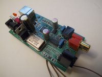
Can anyone help me with this? I've attached a picture of the USB converter board, a copy of the DAC/output stage of my CD player, and the datasheet for the YM3414 receiver chip for reference.
I disconnected the DAC/output stage from the Main PCB and left XTAL dangling since it's not needed by the USB board.
From the USB board I connected DATA to SDI (Pin 7) on the YM3414, LRCK to SDSYS (Pin 6), and SCLK to BCI (Pin 5). I connected GND to a ground point on the CD player.
I'm testing with AIFF files with 16/44.1 sampling.
Help?
Attachments
Good job so far!
There is talk of attenuating the 1541 I2S levels but this has to do with cleaning up a digital signal and doesn't lead to 'overdriven' analog output. So don't worry about that right now.
It sound like you might be sending the 1541 24 bits worth of data and it can only accept 16 bits so the resulting waveform is "too loud"
Are you able to change the bit depth (16, 24 bit) and rate (44, 48, 96, 192 ...)?
Cheers,
Jeff
Shouldnt work with YM, it wants 384Fs MCLK, but Tenor AFAIK supplies 256Fs.
Bypass YM (don't break it, just cut traces between YM and TDA), feed TDA from Tenor.
This way you loose rather nice digital filter... uh... and go rather creepy route of NOS /some may argue, so i'll tag it "IMHO"/
Bypass YM (don't break it, just cut traces between YM and TDA), feed TDA from Tenor.
This way you loose rather nice digital filter... uh... and go rather creepy route of NOS /some may argue, so i'll tag it "IMHO"/
Last edited:
Good job so far!
It sound like you might be sending the 1541 24 bits worth of data and it can only accept 16 bits so the resulting waveform is "too loud"
Are you able to change the bit depth (16, 24 bit) and rate (44, 48, 96, 192 ...)?
I am using iTunes on an old PowerPC based Mac running OS 10.4. I played a CD and 16/44.1 AIFF files with the same result. Is it possible that iTunes is sending 24 bits?
Shouldnt work with YM, it wants 384Fs MCLK, but Tenor AFAIK supplies 256Fs.
Bypass YM (don't break it, just cut traces between YM and TDA), feed TDA from Tenor.
This way you loose rather nice digital filter... uh... and go rather creepy route of NOS /some may argue, so i'll tag it "IMHO"/
Please correct me if I'm wrong (which I probably am), but I got the impression that the YM would be happy with anything 16/44.1 that got sent its way since it has its own clocking from an oscillator on the PCB and doesn't require an MCLK signal.
Last edited:
I am about to buy the same board with I2S output. Is it transparent, meaning if I play 16-bit/44.1kHz WAV file on my PC and send it to the USB, will the board send the same bit resolution and bitrate to the I2S pins? Also does Windows XP recognize the board as external USB DAC? Finally, what is the function of the little switch? Thanks.
I am about to buy the same board with I2S output. Is it transparent, meaning if I play 16-bit/44.1kHz WAV file on my PC and send it to the USB, will the board send the same bit resolution and bitrate to the I2S pins? Also does Windows XP recognize the board as external USB DAC? Finally, what is the function of the little switch? Thanks.
Those are good questions. The little switch is for switching between USB power and an external power source. I'm not sure about Windows XP specifically, but I can tell you that it is a USB audio class 1 device. As for transparency, I have no idea. Maybe somebody else has the answer to that?
Hi there,
If you bypass the filter, you may have to reroute pin27 of the tda1541 also. On your cdp it's connected to - 5v, IIRC on the saa7220 based players it was connected to +5v. I MIGHT BE WRONG!! (check the data sheet!) This pin sets the input mode of the tda to accept different formats
-5v is simultaneous mode whereas +5v is TWC, I think you need twc if you go direct. Apologies, writing this on a phone so no access to the data sheets!
Hi there,
If you bypass the filter, you may have to reroute pin27 of the tda1541 also. On your cdp it's connected to - 5v, IIRC on the saa7220 based players it was connected to +5v. I MIGHT BE WRONG!! (check the data sheet!) This pin sets the input mode of the tda to accept different formats
-5v is simultaneous mode whereas +5v is TWC, I think you need twc if you go direct. Apologies, writing this on a phone so no access to the data sheets!
I would agree if I was going directly into the TDA1541A. But I was thinking that if I have to resort to bypassing the filter chip, I could do it right at the output of the filter, and take advantage of the circuit that appears to reclock (?) and split the signal into left and right channels. Then, I believe, I don't need to change the H/L value at pin27.
Last edited:
Hi there,
If you bypass the filter, you may have to reroute pin27 of the tda1541 also. On your cdp it's connected to - 5v, IIRC on the saa7220 based players it was connected to +5v. I MIGHT BE WRONG!! (check the data sheet!) This pin sets the input mode of the tda to accept different formats
-5v is simultaneous mode whereas +5v is TWC, I think you need twc if you go direct. Apologies, writing this on a phone so no access to the data sheets!
Oh man, you're totally right. I thought the filter chip was outputting an I2S signal, but it's not.
I gave up on running it through the filter. I patched it directly into a TDA1541 in another old CD player with tube output stage for some NOS action. It sounds decent, but not yet as good as from the CD player's transport. I'm hoping that an external power upgrade will help.
Somewhere on this forum I once read that the TE7022 relays information in 24/96 format, even when receiving 16/44.1 data. I suspect that this is true, and that's why I was having trouble patching into the YM3414 filter chip, which seems to require 16 bit "words". (Apparently the TDA1541 is friendlier to 24 bit data, simply ignoring the last 8 bits.)
If you are looking for 16 bit, JarekC makes a board that he can configured to send in 16 bits. I'm not sure if it's "transparent" with respect to sampling frequency though.
http://www.diyaudio.com/forums/digi...nous-usb-i2s-spdif-converter-24bit-96khz.html
- Status
- This old topic is closed. If you want to reopen this topic, contact a moderator using the "Report Post" button.
- Home
- Source & Line
- Digital Line Level
- Hacked TDA1541 CD Player USB DAC Idea