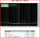
misreading Putzeys? - the Baxandall "harmonic growth" plot doesn't even have 9th on it - with a -120 dB floor
- is meaningless - by itself - most can't hear the 9th harmonic of 2 kHz
feedback reduces all the errors it can measure by the loop gain at that frequency
IMD products folding down into the audio band are in fact reduced by the excess loop gain at those audio frquencies
modest priced soundcard with indifferent JRC V-mode op amps, Delta-Sigma ADC and DAC - can't see 9th at -130 dB
double the frequency so that the 9th is at the upper edge of aubibility and the the single pole compensated op amps are only expected to do 6 dB worse from the loop gain roll-off
Then work out how much feedback is needed to get the same high order distortion performance (talking here 9th harmonic and above) at the top end of the audio band as against an open loop design.
- is meaningless - by itself - most can't hear the 9th harmonic of 2 kHz
feedback reduces all the errors it can measure by the loop gain at that frequency
IMD products folding down into the audio band are in fact reduced by the excess loop gain at those audio frquencies
modest priced soundcard with indifferent JRC V-mode op amps, Delta-Sigma ADC and DAC - can't see 9th at -130 dB
double the frequency so that the 9th is at the upper edge of aubibility and the the single pole compensated op amps are only expected to do 6 dB worse from the loop gain roll-off
Attachments
Last edited:
@ALD - I suspect the reason for the good sound is lower intermodulation distortion. Its a big challenge in I/V amps to get decent IMD performance, having feedback makes it even harder to get lower IMD.
Perfect! Specifics?
George: I have scoped it, with a 200meg Tek with all my tech bench test disc's till I was xeyed. Stable as rock under all conditions.
IMD. I'm guessing it won't be a test track but more of a test situation. Freqs involved in IMD will be much higher and involve freqs from the workings of the DAC and freqs picked up from other parts of the circuit, RFI, EMI, etc... again I await those who work with this stuff in their dayjobs and know what they're talking about to chime in ... I just try to restate things at different levels ...
George: I do have 2mV of very high noise now on the output, but it's so high even the scopes 20mhz filter doesn't touch it, I scoped it all the way back to the PCM1704's itself giving it out, nothing to do with the AD844's or buffers.
I may be over-thinking it but the way you phrase "nothing to do ..." suggests to me a slight refocusing. This isn't about "blaming" the 844 or buff or any other part of the circuit for producing high freqs but ...
rather a shift to another mode of analysis where the environment itself is full of high freqs and its about how different parts of the circuit respond and "handle" this "fact of life."
... wow, can you ever tell I'm having marital problems right now ...
George, when can you next spark up the 'scope?
P.S. Depending on what the experts say, that 2mV high freq could be used as an IMD test signal that we follow through your circuit and see how the different parts "handle it" as they simultaneously try to pass all the other frequencies ...
Last edited:
AD844
Hi AudioLapDance, You asked me about the current nulling on the 1541. On my first build with GIC filter I have a coupling cap after the I/V. That was part of the GIC filter design that dates back to 1991 issue of the Audio Amateur magazine. I believe the author was Paul Marchell (?) So long ago. I have a second build and used the Pedja 2SK170 JFET current source as in the Aya II dac. Here is what happened. I messed up and put the part in backwards (JFET's). The end result was I fried 2 AD844's. My 1541A S1 Crown dac was unharmed. Replaced the JFET's this time with correct orientation. Installed 2 replacement 844's and all was well. It was good enough to direct couple the 844's to the filter. The second build is my experimental platform. I was very surprised! Using cheap Edcor 600/600 transformer with 4n7 polystyrene cap across the primary as a filter the sound was really clear and measured well. My experimental unit has EC Designs and Thorsten style grounding around the dac. The current version of the second build outperforms my first one and is getting an enclosure. I plan to experiment with NOS this summer. Dave
Hi AudioLapDance, You asked me about the current nulling on the 1541. On my first build with GIC filter I have a coupling cap after the I/V. That was part of the GIC filter design that dates back to 1991 issue of the Audio Amateur magazine. I believe the author was Paul Marchell (?)
So long ago. I have a second build and used the Pedja 2SK170 JFET current source as in the Aya II dac. Here is what happened. I messed up and put the part in backwards (JFET's). The end result was I fried 2 AD844's. My 1541A S1 Crown dac was unharmed. Replaced the JFET's this time with correct orientation. Installed 2 replacement 844's and all was well. It was good enough to direct couple the 844's to the filter. The second build is my experimental platform. I was very surprised! Using cheap Edcor 600/600 transformer with 4n7 polystyrene cap across the primary as a filter the sound was really clear and measured well. My experimental unit has EC Designs and Thorsten style grounding around the dac. The current version of the second build outperforms my first one and is getting an enclosure. I plan to experiment with NOS this summer. DaveAudioLapDance;3486913 George: [I said:I do have 2mV of very high noise now on the output, but it's so high even the scopes 20mhz filter doesn't touch it, I scoped it all the way back to the PCM1704's itself giving it out, nothing to do with the AD844's or buffers.[/I]
P.S. Depending on what the experts say, that 2mV high freq could be used as an IMD test signal that we follow through your circuit and see how the different parts "handle it" as they simultaneously try to pass all the other frequencies ...
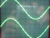
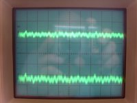
This noise on the rca's is I think the staircase noise in the pic (20khz 0dbf), no LP fitering at all from the dac to the rca's. I prefer to listen with the noise present and no lp fitering at all. As it's so high, way over 20mhz as the 20mhz fiter on my scope dos'nt touch it. As Terry "Zenelectro" said to me a while back about these noises, "trust your ears and not your eyes in some cases" I also believe the AMR CD77 that Thorsten Losetch designed, someone here said it has a lot of HP crap on it's rca outputs as well becase it can cause trouble with certain smp supplies on amps.
Cheers George
Attachments
George - on the PCM1704s, you need to read the datasheet more carefully. 'Glitch free' becomes, on closer inspection 'no glitch around zero' and 'meets THD+N specs without external deglitcher'. R2R based DACs are the glitchiest due to the switches needing perfect synchronization.
Broadly there are two kinds of glitches in DACs - those caused by switch timing mis-matches and those from digital crosstalk. With the co-linear architecture the biggest glitches occur as the -6dBFS amplitude level is crossed. This occurs because the MSB's switching on time doesn't precisely match the remaining LSBs switch off time.
Broadly there are two kinds of glitches in DACs - those caused by switch timing mis-matches and those from digital crosstalk. With the co-linear architecture the biggest glitches occur as the -6dBFS amplitude level is crossed. This occurs because the MSB's switching on time doesn't precisely match the remaining LSBs switch off time.
...part in backwards (JFET's). The end result was I fried 2 AD844's. My 1541A S1 Crown dac was unharmed...
My 1541 S1 crown just quivered in its electrostatic bag! It's ok my precious it's ok, shhh shhhhhh.Details please! Circuit?
And how about this new version? I just happen to have some cheap Edcor WSM10k/10k here that would be honoured to try an I/V job! Circuit?
Cheers,
Jeff
Last edited:
AD844
Hi George, I see the AD844 is available in SOIC 16. Might be easiest to get SOIC 16 to DIP 16 adapter boards and stack the chips with a small air gap and run to a 8 pin DIP header to get to a Dip socket. Use a bus wire to parallel the needed pins down to a header. That avoids thick DIP parts soldered directly together. Allows some air cooling too if needed. Just a thought.... Dave
Hi George, I see the AD844 is available in SOIC 16. Might be easiest to get SOIC 16 to DIP 16 adapter boards and stack the chips with a small air gap and run to a 8 pin DIP header to get to a Dip socket. Use a bus wire to parallel the needed pins down to a header. That avoids thick DIP parts soldered directly together. Allows some air cooling too if needed. Just a thought.... Dave
I monitored the temp of mine, and they sit about 35c. The thing to monitor I've read is the dac when getting the I/V's impedance down low.
As in Supra said two pages back, and on another 844 forum in Aus he is going to do 5 stack for his TDA1541 he was so impressed with two. Five will give him a 10ohm load as seen by his TDA1541 that could make it warm?
Cheers George
As in Supra said two pages back, and on another 844 forum in Aus he is going to do 5 stack for his TDA1541 he was so impressed with two. Five will give him a 10ohm load as seen by his TDA1541 that could make it warm?
Cheers George
AD844
Hi George, My understanding is that the TDA1541A will withstand a direct short and the heat radiated is just slightly more at just over 1 Watt or so. It doesn't rise much making music once up to temperature. I made a small heatsink for mine that uses special "thermal" double sided tape sold for video cards. I found that stuff on ebay. In case you'd like to try that. I am trying to preserve the 2 S1 Crown dacs that I have for as long as possible. I purchased mine in the early 1990's and my Cousin gave me his a few years ago. These are from long before the fake stuff appeared. I'm sure I will never see the real ones again..... Dave
Hi George, My understanding is that the TDA1541A will withstand a direct short and the heat radiated is just slightly more at just over 1 Watt or so. It doesn't rise much making music once up to temperature. I made a small heatsink for mine that uses special "thermal" double sided tape sold for video cards. I found that stuff on ebay. In case you'd like to try that. I am trying to preserve the 2 S1 Crown dacs that I have for as long as possible. I purchased mine in the early 1990's and my Cousin gave me his a few years ago. These are from long before the fake stuff appeared.
I'm sure I will never see the real ones again..... DaveI don't use the TDA1541 Dave, I have PCM1704 which are much lower in output 1.2mA, compared to the TDA5141's 4mA, this is why believe 2 stack 844's with the PCM1704 is the ideal where maybe 4 stack with the TDA1541 would be the ideal having more than double the output. If current starvation is an issue with either the signal or the glitches with these 844's. Or as I said before maybe I'm hearing the difference of 50ohm 1 x 844 loading of the PCM1704 compared to 25ohm 2 x 844's.
Cheers George
Cheers George
I don't use the TDA1541 Dave, I have PCM1704 which are much lower in output 1.2mA, compared to the TDA5141's 4mA, this is why believe 2 stack 844's with the PCM1704 is the ideal where maybe 4 stack with the TDA1541 would be the ideal having more than double the output. If current starvation is an issue with either the signal or the glitches with these 844's. Or as I said before maybe I'm hearing the difference of 50ohm 1 x 844 loading of the PCM1704 compared to 25ohm 2 x 844's.
Cheers George
George,
It is not quite so simple.
There are a few issues to consider that will cause the I-V to 'fall over'.
1) OP impedance of DAC 2) OP current swing
The low the (internal) OP Z of DAC, the less linear the I-V will be, comparatively speaking. Also a non linear or non resistive DAC OP Z will
cause additional distortion.
Other non linearities are non linear capacitance in I-V. These are voltage dependent capacitances of the semiconductors. This will manifest at
higher frequencies when you start stacking too many 844's there will be a
point that there are more losses than gains.
Another is thermal distortions. When current is modulating power through IP
grounded base stage of 844 the die is heating and cooling causing distortion.
This will manifest more with low OP Z DAC's. By stacking this is reduced.
More in this than you thought hey
With a discrete circuit -all- these distortion mechanisms can be reduced greatly - even without the use of feedback.
Terry
George,
With a discrete circuit -all- these distortion mechanisms can be reduced greatly - even without the use of feedback.
Terry
I also believe discrete would be better again Terry, but the simplicity and massive gains of the use of the 844 when subbing it for a normal 8 pin dil i/v opamps with very few mods is a winner, it can be done in a few minutes by those with very little knowledge.
Then if you go the discrete way this could take a lot longer than that if you could find a proven circuit, even Pedja Rogic said with his discrete clone of 844, it was hard to say if it sounded better than the AD844 itself. And he has not heard the advantage of stacking the 844. And you can still use the good internal buffer it has.
PS: Terry, as you suggested to try, (believe my ears not my eyes) I have taken off lp filtering on the 844 (cap across TZ resistor) and for good measure the LP filter on the input of the buffer I'm using, no noise heard, but I can see it on the scope, I think you were right it does fractionally sound better (more relaxed) with no filtering at all from dac output to rca's, still only 2mV of very high crap on the output rca's.
Cheers George.
Last edited:
...the simplicity and massive gains of the use of the 844 when subbing it for a normal 8 pin dil i/v opamps with very few mods is a winner, it can be done in a few minutes by those with very little knowledge.
Spot on! Sometimes the beauty of diy isn't implementing the perfected-this or the ultimate-that. It is rather the serendipitous and simple combining to achieve an enormous bang-for-buck!
...even Pedja Rogic said with his discrete clone of 844, it was hard to say if it sounded better than the AD844 itself.
Well, he actually said it was close enough to not worry about it too much:
bear in mind that it will not be easy to beat the AD844. The layout and supply have to be done carefully and it worth to check if the output buffer will improve something or not. Ultimately this circuit has less grain and can achieve a better resolution but this does not mean that you will notice the grain or lack of the resolution listening to the common base AD844 I/V, you will not. Other than known shortcomings the monolithic solutions also have some advantages which are not only practical by nature.
from: Pedja Rogic, Discrete Diamond Non-Feedback I/V Stage for TDA1541(A) DAC
And he has not heard the advantage of stacking the 844.
Well, he fully investigated the lack of heavy bias:
Interesting fact is that the AD844's internal circuit (as is) also could achieve superb distortion performance used as a common base stage, but it needs a higher bias current. Some other variation on this theme can perform well too, and some can perform even better. So, the bias used in the AD844 is below what we need here ...
from: Pedja Rogic, Discrete Diamond Non-Feedback I/V Stage for TDA1541(A) DAC
And his discrete circuit addressed it so in a sense he heard higher bias 844.
Last edited:
AD844
Hi Guys, Well I have the DDNF and I did use Pedja's 844 circuit from the Aya II dac. Yes.... I think there are some similarities. In my system they are really not close in sound quality terms. I found the discrete circuit to be very clean and dynamic. The 844 was nice however over time I realized it was just off the mark. The current starvation thing I am sure is the issue. When I get some time I'll need to try a buffer off the TZ point as George suggest. For the TDA1541(A) I'd think the DDNF might be a better match. Maybe adding another discrete current mirror section would be worth a shot. Wish I was up to the task to model that.... Don't have that software or experience. Stacking 2 844's seems worth while. Four is an issue I'd think. ! ? Dave
Hi Guys, Well I have the DDNF and I did use Pedja's 844 circuit from the Aya II dac. Yes.... I think there are some similarities. In my system they are really not close in sound quality terms. I found the discrete circuit to be very clean and dynamic. The 844 was nice however over time I realized it was just off the mark. The current starvation thing I am sure is the issue. When I get some time I'll need to try a buffer off the TZ point as George suggest. For the TDA1541(A) I'd think the DDNF might be a better match. Maybe adding another discrete current mirror section would be worth a shot. Wish I was up to the task to model that....
Don't have that software or experience. Stacking 2 844's seems worth while. Four is an issue I'd think. ! ? Dave Dave what buffer were you trying this time? Hope you weren't trying to drive from the TZ, as that is sad, it has an output impedance some say of 3 megohm, it really needs to see the direct input of a fet buffer or tube with no loading resistors, just like it see it's own internal buffer inside the AD844, and that adds to it as well, as it cannot be disconected.
Re stacking with the TDA1541 Supra (Mick) over on a nother AD844 forum that's going, tried 3 and thought it was great, went to 4 and is thinking it maybe a bit too tight & hifi sounding, but he said in some systems it could be just right.
It's a bit like loading down a moving coil cartridge, as I remember with a Supex 901, it got tighter and tighter and more dynamic sounding the closer it got down to 0ohms loading, and that was system dependant as well, I remember with 50kohms it was sloppy as?
Cheers George
Hi Guys, Well I have the DDNF and I did use Pedja's 844 circuit from the Aya II dac. Yes.... I think there are some similarities. In my system they are really not close in sound quality terms. I found the discrete circuit to be very clean and dynamic. The 844 was nice however over time I realized it was just off the mark. The current starvation thing I am sure is the issue. When I get some time I'll need to try a buffer off the TZ point as George suggest. For the TDA1541(A) I'd think the DDNF might be a better match. Maybe adding another discrete current mirror section would be worth a shot. Wish I was up to the task to model that....
I went to 4 844's on my 1541, it worked perfectly, but I preferred the sound of 3, 4 got a bit "hifi" sounding, it is probably technically better, but moved too far away from "1541" sound, but having said that, this is still the best I've ever heard the 1541 sound, and by a large margin. I have a stack of very expensive good "modern" dacs here and I'm enjoying the old 1541 very much.
I do think the Rogic 2SK170B buffer I'm using is contributing to sound, very good power supply, good layout etc.
I've been known to be very critical of the hype around the old 16 bit dac chips, and I must admit this has surprised me greatly. I tried a few 844 variations 10 years ago, wish I ad realised the advantages of stacking them then.
AD844
Hi George, Yes... I know it has to be buffered from the TZ pin 5 connection. It's on my to do list. 3 Megohms doesn't leave many options. The discrete buffers in the thread or maybe the antiquated BUF03. I have a pair of LT1010's however I need to check the datasheet as to the input impedance. My comments are about Pedja's pin 6 normal output schematic on the Aya II dac. I need to order up a few 844's. I'm lucky that the board I built my circuit on still has enough room to add the buffer. Hi supra, Thanks for the suggestion on 3 844's. I do think there may be a limit on paralleling devices. I remember seeing TDA1543's stacked up in another thread. Like domino's. Wonder what that sounded like? ! 
Hi George, Yes... I know it has to be buffered from the TZ pin 5 connection. It's on my to do list. 3 Megohms doesn't leave many options. The discrete buffers in the thread or maybe the antiquated BUF03. I have a pair of LT1010's however I need to check the datasheet as to the input impedance. My comments are about Pedja's pin 6 normal output schematic on the Aya II dac. I need to order up a few 844's. I'm lucky that the board I built my circuit on still has enough room to add the buffer. Hi supra, Thanks for the suggestion on 3 844's. I do think there may be a limit on paralleling devices.
I remember seeing TDA1543's stacked up in another thread. Like domino's. Wonder what that sounded like? ! I went to 4 844's on my 1541, it worked perfectly, but I preferred the sound of 3, 4 got a bit "hifi" sounding, it is probably technically better, but moved too far away from "1541" sound,....
I wonder if your experience might be partly explained interms of the TDA1541's THD output characteristics with different I/V values.
Apparently the minimal THD occurs with an I/V resistance of <13ohms.
If the AD844 has an input impedance of 50ohms the THD of the TDA1541 can be expected to drop with stacking.
I wonder if the romantic coloration traditionally ascribed to the TDA1541 is not an intrinsic property of the chip but due to the induced THD with a too high I/V stage?
Hi George, Yes... I know it has to be buffered from the TZ pin 5 connection. It's on my to do list. 3 Megohms doesn't leave many options.
Now I'm lost - in my understanding you're using the AD844 open loop as a transimpedance amp where the gain is set by the resistor hung off pin5. So then the impedance at pin5 is just the impedance you hang off it, and the 3M is in parallel with that resistor.
Anyone tried a very low impedance shunt yet on their AD844s supply?
- Home
- Source & Line
- Digital Line Level
- Using the AD844 as an I/V