Hmm, TINA doesn't have the 2SK246 or 2SJ103 FETs
2SK246 Semiconductor (Transistor, diode, IC) Cross reference
Lists 2N5457, 2SK330 as replacements for the 246 and 2N5460, 2N5463, 2SJ105 as replacements for the 103
TINA does have the 2N5457 (for the K246) and 2N5460 (for the J103)
2SK246
View attachment 2SK246 FET 388279_DS.pdf
2SJ103
View attachment 2SJ103_datasheet_en_20071101.pdf
...
Hmm, TINA doesn't have the 2SK246 or 2SJ103 FETs
2SK246 Semiconductor (Transistor, diode, IC) Cross reference
Lists 2N5457, 2SK330 as replacements for the 246 and 2N5460, 2N5463, 2SJ105 as replacements for the 103
TINA does have the 2N5457 (for the K246) and 2N5460 (for the J103)
2SK246
View attachment 332846
2SJ103
View attachment 332850
...
If you can find the Spice model for those transistors, it's easy to create a macro for them. Let me know and I can help.
...
TINA has no 2SC2240
Replacements: 2SC2362, 2SC2389, 2SC2459, 2SC2631...32
BFR86 2N2509
TINA has none of these
TINA has no 2SA970
Replacments: 2SA1038, 2SA1049, 2SA1123, 2SA1136
2SB789 KT632B
TINA has none of these
Other replacements for the 2SC2240 NPN and 2SA970 PNP?
Thanks,
Jeff
2SC2240
View attachment 2SC2240 npn 968.pdf
2SA970
View attachment 2SA970 pnp 962.pdf
I don't agree that "cable filtering", by which I assume you mean filtering the signal at the cable connector on the chassis, is a serious weakness nor a serious problem for well designed cables. I use Canare Star Quad cable, which is designed to dramatically reduce RF interference. See the attached document for reference.
That will improve matters for the signal cables I agree, assuming you're using 360 degree termination at the shell of the XLRs. However a chain is only as strong as its weakest link - what kind of cable are you using for mains supply? I see no mains inlet filtering.
Last edited:
.MODEL 2SC2240 NPN (IS=9.98557F BF=444.22 NF=965.739M VAF=439.144 IKF=99.567M
+ ISE=6.48962F NE=1.29179 BR=425.865M IKR=954.972 ISC=539.648P RC=168.128M
+ CJE=2P MJE=500M CJC=11.7089P VJC=750.026M MJC=499.123M TF=1.41635N
+ XTF=499.995M VTF=10 ITF=10.055M TR=10N )
Dear sir, where did you find these fine models?
Teach a man to fish and all ......I'm very interested to see what the input (with & without the 100k) and output impedances are.
I may try this straight from the TZ of the AD844 next weekend
...

By "straight from the TZ" did you mean:

Dear sir, where did you find these fine models?
Extensive Google searching. A lot of them are right here on DIYAudio, but buried deep...
That will improve matters for the signal cables I agree, assuming you're using 360 degree termination at the shell of the XLRs. However a chain is only as strong as its weakest link - what kind of cable are you using for mains supply? I see no mains inlet filtering.
I checked the output from the regulators I am using and there is no line noise that I can see. There's just a tiny amount of clean residual on the outputs. So, no special cable is required in my application.
Ok, imported the transistor files and added a few more test points
1: PCM1704
2: AD844 Pin 5
3: buf in (sort of, to see the roll-off of the buffer input filter)
4: buf out

And here's what you get to 10GHz

And here's an audio friendly 10 to 10MHz

And here's a 1kHz square wave, 0.6mA pk, 1ns rise time

Hmmm ... note different 'dc' levels ...
1: PCM1704
2: AD844 Pin 5
3: buf in (sort of, to see the roll-off of the buffer input filter)
4: buf out
And here's what you get to 10GHz
And here's an audio friendly 10 to 10MHz
And here's a 1kHz square wave, 0.6mA pk, 1ns rise time
Hmmm ... note different 'dc' levels ...
Last edited:
Extensive Google searching. A lot of them are right here on DIYAudio, but buried deep...
I was hoping you knew some magic site ...
Would imported spice models of 2SK246 and 2SJ103 FETs be more accurate than the "equivalent" FET models (2N5457 for the K246 and 2N5460 for the J103) in TINA that I'm using now?
Cheers,
Jeff


I was hoping you knew some magic site ...
Would imported spice models of 2SK246 and 2SJ103 FETs be more accurate than the "equivalent" FET models (2N5457 for the K246 and 2N5460 for the J103) in TINA that I'm using now?
Cheers,
Jeff
I don't know, but it's worth a try. The included models have a bunch of parameters that you can compare with the .lib file you get on those transistors. I don't know what a lot of it means....
You can also grab all of Bob Cordell's models as well. Maybe there's something useful in there.
There are some things in Tina that I've never figured out how to use. The digital storage scope, for example. It confuses me and the help menu is poor as far as I can see.
Last edited:
Come see what I caught! First time fishing and I caught 4 big, fat JFET spice models!
They were T H I S big, I swear!
Hi Giovanni,
J-fet models as per your request...I would use 2SK170/2SJ74 cascoded by 2SK246/2SJ103(Erno Borbely style)...and use low Cob transistors instead BD139/140 (like BF472/473 or better)
.model 2SK246 NJF(Beta=1.07m Rs=56.76 Rd=56.76 Betatce=-.5 Lambda=2.8m Vto=-2.638 Vtotc=-2.5m Cgd=10.38p M=.4373 Pb=.3905 Fc=.5 Cgs=6.043p Isr=112.8p Nr=2 Is=11.28p N=1 Xti=3 Alpha=10u Vk=100 Kf=1E-18 Af=1)
.model 2SJ103 PJF(Beta=2.197m Rs=76.76 Rd=76.76 Betatce=-.5 Lambda=735.3u Vto=-2.037 Vtotc=-2.5m Cgd=18.95p M=.5045 Pb=.3905 Fc=.5 Cgs=17.02p Isr=38.48f Nr=2 Is=3.848f N=1 Xti=3 Alpha=10u Vk=100 Kf=1E-18 Af=1)
.model 2SJ74 PJF(Beta=92.12m Rs=7.748 Rd=7.748 Betatce=-.5 Lambda=4.464m Vto=-.5428 Vtotc=-2.5m Cgd=85.67p M=.3246 Pb=.3905 Fc=.5 Cgs=78.27p Isr=129.8p Nr=2 Is=12.98p N=1 Xti=3 Alpha=10u Vk=100 Kf=26.64E-18 Af=1)
.model 2SK170 NJF(Beta=59.86m Rs=4.151 Rd=4.151 Betatce=-.5 Lambda=1.923m Vto=-.5024 Vtotc=-2.5m Cgd=20p M=.3805 Pb=.4746 Fc=.5 Cgs=25.48p Isr=84.77p Nr=2 Is=8.477p N=1 Xti=3 Alpha=10u Vk=100 Kf=111.3E-18 Af=1)
They were T H I S big, I swear!
Last edited:
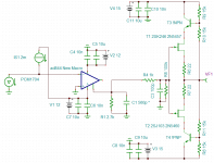
Here's George's updated circuit with the spice models of the real 2SK246 and 2SJ103 FETs rather than 'replacements' that just happen to be in TINA.

(I added 20k load to the ouput of the JFET buffer and also added 20k load to the output pin 6 of the AD844, should pin 6 be loaded in reality too?)
The freq from 10 to 10GHz

And here's a 1kHz square wave, 0.6mA pk, 1ns rise time

And the TINA schematic
View attachment ad844 IV PCM1704 + FET buffer.zip
Cheers my friend!
PS Now if we could just figure out how to do all the fancy sims and tests, we'd really harness the power of TINA!
(I added 20k load to the ouput of the JFET buffer and also added 20k load to the output pin 6 of the AD844, should pin 6 be loaded in reality too?)
The freq from 10 to 10GHz
And here's a 1kHz square wave, 0.6mA pk, 1ns rise time
And the TINA schematic
View attachment ad844 IV PCM1704 + FET buffer.zip
Cheers my friend!
PS Now if we could just figure out how to do all the fancy sims and tests, we'd really harness the power of TINA!
Last edited:
OK thanks Jeff, while you were tampering with Tina (hope she's a good looker) I was instaling the discrete buffer. It's hard to hold back but I will wait till I listen more over the weekend, but the AD844 holy grail has just shifted to another level.
This discrete buffer was also looked at by John Curl and he liked what he saw and said that it was a good design. I had to change TZ resistor and cap to 3.3kohm and 420pf because I needed a touch more gain from the I/V.
Cheers George
This discrete buffer was also looked at by John Curl and he liked what he saw and said that it was a good design. I had to change TZ resistor and cap to 3.3kohm and 420pf because I needed a touch more gain from the I/V.
Cheers George
3.3k, 420p

Freq

Square

Oh and if it was me, I'd get like a 3rd, 4th and 5th opinion (no offense guys) before I'd hook up a cap across a precious DAC .... Yessss, my preccccccciousssssss
PS You da man for actually trying these experiments, I'll be joining you soon ...
Freq
Square
Oh and if it was me, I'd get like a 3rd, 4th and 5th opinion (no offense guys) before I'd hook up a cap across a precious DAC .... Yessss, my preccccccciousssssss
PS You da man for actually trying these experiments, I'll be joining you soon ...
Last edited:
- Home
- Source & Line
- Digital Line Level
- Using the AD844 as an I/V