Back to AD844 common base iv!
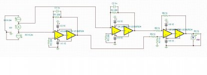
AD844/TDA1541A schematic:

Hmm, tried to sim the 1541 as a 'current generator' with 10mA DC offset, 2mA. (Is it 10mA sink?) And then cancelled it with a 10mA current sink instead of the little FET circuit from the schematic.
AD844/TDA1541A freq resp

-3dB @ 100k
63dB gain ?!? Hmmm, that's not right ...?!?
AD844/TDA1541A tina file
View attachment ad844 IV TDA1541.zip
Anybody know how to model a current DAC in Tina (better yet TDA1541A and PCM1704!)?
Thanks,
Jeff
AD844/TDA1541A schematic:
Hmm, tried to sim the 1541 as a 'current generator' with 10mA DC offset, 2mA. (Is it 10mA sink?) And then cancelled it with a 10mA current sink instead of the little FET circuit from the schematic.
AD844/TDA1541A freq resp
-3dB @ 100k
63dB gain ?!? Hmmm, that's not right ...?!?
AD844/TDA1541A tina file
View attachment ad844 IV TDA1541.zip
Anybody know how to model a current DAC in Tina (better yet TDA1541A and PCM1704!)?
Thanks,
Jeff
Last edited:
Anybody know how to model a current DAC in Tina?
I've done it in LTSpice. Never used Tina.
I already did - perhaps you came to the party late 
http://www.diyaudio.com/forums/digital-source/227677-using-ad844-i-v-2.html#post3328462
The first attachment contains the schematic.
http://www.diyaudio.com/forums/digital-source/227677-using-ad844-i-v-2.html#post3328462
The first attachment contains the schematic.
I already did - perhaps you came to the party late
http://www.diyaudio.com/forums/digital-source/227677-using-ad844-i-v-2.html#post3328462
The first attachment contains the schematic.
Whoa! So let me get this straight ... this is a current waveform generator that outputs a copy of the current that actually comes out of a TDA1541A?
Hmmm, not sure how to get your .asc file into Tina
Tried opening it in notepad and renaming it .cir
Keep getting 'error loading library' ...
Helppppppp ...
PS And I changed by 1541 current source Tina model to 2mA offset and 2mA (pk to pk) output. Is that right?
Last edited:
.asc is the schematic file type, proprietary to LTspice like a CAD .dwg or similar
it really takes ~10 min on a fast connection to be up and running LTspice
you should be able to load the .asc in LTspice then copy the generated Spice netlist to most Spice programs - but you won't have the nice schematic
it really takes ~10 min on a fast connection to be up and running LTspice
you should be able to load the .asc in LTspice then copy the generated Spice netlist to most Spice programs - but you won't have the nice schematic
Whoa! So let me get this straight ... this is a current waveform generator that outputs a copy of the current that actually comes out of a TDA1541A?
No - where did that idea come from? Its a current source which reproduces the waveform from a .wav file.
Well its jolly hard to come up with a detailed model for the TDA1541A without knowing the internal schematic. I think perhaps Thorsten knows something about that as he said he got a pile of papers from the original designers. On the 1704 you could start with two R2R networks and switches but it wouldn't get you very far. The primary difference between DACs in terms of sound I reckon is glitch performance and modelling that is very hard indeed.

AD844/TDA1541A freq resp
View attachment 330117
-3dB @ 100k
63dB gain ?!? Hmmm, that's not right ...?!?
AD844/TDA1541A tina file
View attachment 330120
Anybody know how to model a current DAC in Tina (better yet TDA1541A and PCM1704!)?
Thanks,
Jeff
63dB is not far off. I think in the 50's is about normal.
I use Tina a lot. I use a current generator, set to 1Mohm internal impedance. I think use external current sources to simulate the DC offset.
Attachments
sure, cahnge the Isource to a full scale p-p pulse with ns edge rate
Thanks, this sounds like it will provide some of the staircase current waveform. What the DAC puts out.
What I'm also looking for, is more info on how the 1541 1704 "looks": RLC, like dirkwright's suggestion to change the "internal impedance" to 1M instead of infinite.
Last edited:
How is Tina calculating this? Usually gain is Vo/Vi but we have Vo/Ii?63dB is not far off. I think in the 50's is about normal...
...
. I think use external current sources to simulate the DC offset.
The first menu of the current generator has a "DC level [A]" which I set to 2m for the 2mA offset.

No need to run the AD844 with an output-cap..!!
It has a maximum of 50uV thermal drift and can be offset adjusted either by the DAC counter-current or by adjusting the offset by trimmer like in page 16 of the AD844 Datasheet. To maintain DC coupling there is the task of getting the thermal-drift of the DAC and the counter current stable.
It has a maximum of 50uV thermal drift and can be offset adjusted either by the DAC counter-current or by adjusting the offset by trimmer like in page 16 of the AD844 Datasheet. To maintain DC coupling there is the task of getting the thermal-drift of the DAC and the counter current stable.
With my i/v 844 with or without inbuilt buffer in circuit, with Abraxalito's dc offset circuit between dac and 844 input I can get the dc offset stable to within +- .5mV on the output of the 844, so a dc coupling cap is definately not needed.
I hate caps in the signal path, I can always hear them no matter how good they are compared to direct coupled. One proviso you my get a small switch on or off thump, but I think this would happen anyway with a coupling cap as well.
Cheers George
I hate caps in the signal path, I can always hear them no matter how good they are compared to direct coupled. One proviso you my get a small switch on or off thump, but I think this would happen anyway with a coupling cap as well.
Cheers George
How is Tina calculating this? Usually gain is Vo/Vi but we have Vo/Ii?
The first menu of the current generator has a "DC level [A]" which I set to 2m for the 2mA offset.
View attachment 330372
If you use a probe, you can see that there is a small voltage at the input to the opamp from the current generator. I assume that it is using that voltage to calculate gain.
Setting the DC current level in the generator is fine for single ended operation, but the PCM1794 I was trying to simulate has balanced outputs with DC current in the same direction on both of them. I don't know about the DAC you are trying to simulate.
After listening now for a while, I get the best sound taking the signal from TZ of the AD844 2.7k & 560pf to ground, then to my opamp based LP filter (AD825 as 3rd order L/P) The inbuilt buffer when used of the 844 has a touch of 2 dimentional sterility to it, not as good as coming straight off the TZ.
Now here is something that had me scratching my head, what do you guys think of it, I removed the 560pf which I believe is a 1st order L/P at –3db 105khz , you would think that having no 1st order l/p filter except still for the 3rd order 825 opamp I would see just a little more noise on the output, but nothing worth mentioning. But the sound difference if anything should have been a little more emphasis maybe in the top end, but no the opposite happened, I got a more relaxed presentation of the top end, still just as detail but a little laid back than with the 560pf attached. The only thing I can think of that the output of the I/V stage is not dynamically stable under musical conditions with the 560pf capacitor loading, and maybe it is a little unstable and can ring/oscillate a little with any caps on it to ground and makes the topend sound a little peaked?
Cheers George
Last edited:
- Home
- Source & Line
- Digital Line Level
- Using the AD844 as an I/V