I'm surprised that the output SR is as low as 96kHz - those 'spiral' oscillations on the 20kHz sine look to have an envelope frequency around 16X which to me suggests the PCM1704 is running at 384kHz (8X OS).
Have you tried running NOS? You'll notice an improvement in the dynamics.
Have you tried running NOS? You'll notice an improvement in the dynamics.
I prefer the PMD200 on HDCD recordings. (is this nos as the upsamling light is not on just the hdcd light)
On standard redbook I just prefer the upsampling mode which the upsampling light comes on only.
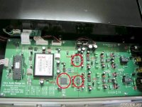
As far as doing NOS I would not know where to start or if it is possible attached is a pic of the board.
There more info on the first page of the filtering on this Stereophile review here. Measurements came up good too
http://www.stereophile.com/cdplayers/504cary/index.html
Cheers George
On standard redbook I just prefer the upsampling mode which the upsampling light comes on only.
As far as doing NOS I would not know where to start or if it is possible attached is a pic of the board.
There more info on the first page of the filtering on this Stereophile review here. Measurements came up good too
http://www.stereophile.com/cdplayers/504cary/index.html
Cheers George
Attachments
Last edited:
Changed the TZ resistor/cap from 2.7k/500pf to 3k/1200pf to give me a touch more gain and filtering to see if it effects the spiral oscillation (you were right they were the steps as looked without any cap and the spiral turned into clear steps) and didn't change with either the DF1704 or the PMD200 switched in.
With the 3k and 1200pf (-3db @ 42.3khz) on TZ, all is clear now with the 20khz sine wave, just the smallest hint of spiral remains if zoomed in on. And I'm just a touch down on frequency response approx 1dB at 20khz. I'll have a listen later, probably won't hear any difference with this change, but it looks better on the scope and that's a good mental thingy.
While I was at it as you know I'm using the 844's buffer straight to the rca's which should be by the data sheet 15ohms output impedance, with no load just the scope a 1khz test wave droped 25% with 100ohm loaded, this tell me AD is a little off with their specs of 15ohm.
Cheers George
Last edited:
Abraxalito, please educate me some more, I listened last night (I will do some more tonight) to the above setup TZ with 3k and 1200pf which gave a touch more gain and 1st order filtering at 44khz.
The thing that I noticed again is the bass, seemed to be less defined still had power but less definition, more softened tube like. If I didn't know better it's as though the i/v stage cannot drive the buffer stage as well with this 3k and 1200pf.
The first time I listened to it Pedja's way with 1K and 1000pf ( which I must try it again) I remember I was impressed with the slam and bass definition even though I did not have enough gain with quiet recorded cd's, is it possible that with the the 1k and 1000pf that the I/V stage has better drivability into the buffer than with the 3k and 1200pf?
Maybe this needs to be simmed to see what's going on. But I will have another listen tonight to see if it is what I heard last night.
Cheers George
Last edited:
Hi George - I don't have any experience with open loop TZAs so I'm just guessing here. The grounding point of the parallel RC on this node will be very critical - if you have a groundfill then it will be very hard to decide on the right point to ground it. Why not experiment with different time constants - try with the 3k resistor but only 1000pF and see how that sounds. If this is like my experiments with LM6172 then smaller caps sound better.
I very much doubt that simming it will shed any light on why it sounds different - been there, tried that with my AD1955 DAC about 3 years ago.
I very much doubt that simming it will shed any light on why it sounds different - been there, tried that with my AD1955 DAC about 3 years ago.
Somebody needs to sim this beast!
SPICE Models | AD844 | Analog Devices

Dirkwright simmed an 844 in Tina (just as regular IV)
Hey George, do you wanna give learning Tina a try? It's a powerful tool!
SPICE Models | AD844 | Analog Devices
Dirkwright simmed an 844 in Tina (just as regular IV)
Ok, I modeled this circuit in Tina using Analog's spice model for the AD844....
Hey George, do you wanna give learning Tina a try? It's a powerful tool!
LTspice is good too, some say better if you are looking for "an engineer's Spice"
Mmmm, would that be good for a dry rub on ribs?

Google-ogled the Interwebs for "ad844 iv":
Pedja on 844:
DIYHiFi.org • View topic - Pedja's AD844 I/V stage
…you can use either buffered (pin 6) or unbuffered output (pin 5). But you shouldn't connect these pins one to another, as it will short the buffer input and output. (You can put some small cap across the diamond to improve on its stability but that would be another issue.)
Purely sonically, the buffer you have within AD844 is the good one but, things being said, all the other IC diamond buffers I tried measured better.
…
I did used buffered output of AD844 (pin 6). Unbuffered output sounds more natural but in most cases it lacks the dynamics of the buffered output.
More from Pedja:
DIYHiFi.org • View topic - Let's talk audio design
As for the IC transistor matching and linearity, AD844, which is also similar (diode connected first transistors instead of the real diamond structure), also varies a bit from sample to sample, its current mirrors can show from 0.03% to 0.07% THD under the same conditions as described above. Stereophile measurements of Ayre CX-7 point out the same issue. Anyhow, taking into account internal bias of AD844 (6.5mA for all the arrays), I am convinced that this part can easily do much better, only if someone at AD would like to make possible external biasing. I am not sure they think in this direction though. Other than that, from conversation with Maxim, I indeed realized that linearity wasn’t any priority in case of their 435/436 and for the audio they simply recommend use of feedback.
CG on why many audio opamps are not ideal as IV:
DIYHiFi.org • View topic - I/V on the PCM1704
As has been said a lot of times, current output DACs, audio or not (back to my day job) produce minimum distortion when used into very low impedance loads. Ideally a virtual ground. That's because the current sources used within aren't perfectly linear - they're designed to be monotonically accurate and fast.
Probably 99.985% of every current output DAC implementation used in commercial products for audio has used an opamp as an I/V converter. Why? Because it appears to be the right thing - it says so right there in the data sheet - and they are cheap and repeatable. (So is bad ethnic food...) The problem is that the virtual grounds supposedly found in inverting opamp stages really are only inverting grounds at audio frequencies. Unfortunately, the switching currents at the DAC output are much higher in frequency than that. So much for the virtual ground. If you want to read more about that, Google the name Barrie Gilbert and read what he has to say on the subject. If he isn't qualified enough on the subject for you, you're certainly wasting your time here.
Common base circuits can be made very, very linear and easily enough. Yeah, you can make an opamp work in the circuit, but you have to go to great lengths and use an expensive part. Even then, it may well not sound as good.
Better you should build a simple I/V converter and spend your time and money on improving the power supply and regulation - a whole other topic."
Hmm, didn't Gilbert have something to do with this ... ;-)
Zinsula made an open loop pre with ad844:
DIYHiFi.org • View topic - Op Amp based open loop line amp
He is using it opamp style but Charles Hansen does talk about loading pin 5:
“We have been using a circuit like this for several years in our less expensive products. The sound is *far* beyond normal op-amps (but still not as good as zero-feedback discrete circuits).
One problem with your circuit is that the input offset current will cause problems. Another problem is that when you load down pin 5 with low resistor values (such as the 5k you have shown) then some problems crop up. I will leave it to you to find solutions to these problems.”
Zinsula replies:
“Thank you for the hints, Charles. I'm afraid that I will not see a solution to the problems on a theoretical way, so I have to buy these parts.
Regarding the offset, I think at injecting/sinking current with a ccs.
Regarding the other problem, I'm a little disappointed as I thought to place a pot at pin 5 loading the internal mirrors and having a buffered volume control.
If it is a current limit problem of the mirrors......I do not know their maximum current though. In the AD846 data sheet, which is a similar part, they claim maximum 1mA. So I could increase the resistor at the inverting input(s) to avoid that a signal of say max. 5V will saturate the mirrors even when pin 5 is connected with a very low resistor to ground. Although I believe that AD844 will allow higher currents in the mirrors.
Unfortunately, I can't really find out this from the datasheets. Maybe I'm just not bright enough...”
Here's Zinsula's AD844 circuit:

He goes on:
“Carlos, yes I will look at input network. Charles gave the hint that input offset currents may be an issue with this chip (it has no differential input, and is bipolar). So, a current injection/sinking will be required too...reminds me of your AD815 and the issue is essentially the same.
Jam, what do you mean with "a buffer after the pot"?
There is one, the internal diamond buffer of AD844. It could be replaced by an external one though, as PMA explained.
If it could be done as I have drawn, the potentiometer is in fact "isolated" from the input as well as from the output. It essentially only loads the TZ node, which is no longer a high impedance node and therefore gain of the op amp is reduced. When the TZ node is at 0 Ohms to ground, the output voltage is zero...”
Tidbits to chew upon ...
Pedja on 844:
DIYHiFi.org • View topic - Pedja's AD844 I/V stage
…you can use either buffered (pin 6) or unbuffered output (pin 5). But you shouldn't connect these pins one to another, as it will short the buffer input and output. (You can put some small cap across the diamond to improve on its stability but that would be another issue.)
Purely sonically, the buffer you have within AD844 is the good one but, things being said, all the other IC diamond buffers I tried measured better.
…
I did used buffered output of AD844 (pin 6). Unbuffered output sounds more natural but in most cases it lacks the dynamics of the buffered output.
More from Pedja:
DIYHiFi.org • View topic - Let's talk audio design
As for the IC transistor matching and linearity, AD844, which is also similar (diode connected first transistors instead of the real diamond structure), also varies a bit from sample to sample, its current mirrors can show from 0.03% to 0.07% THD under the same conditions as described above. Stereophile measurements of Ayre CX-7 point out the same issue. Anyhow, taking into account internal bias of AD844 (6.5mA for all the arrays), I am convinced that this part can easily do much better, only if someone at AD would like to make possible external biasing. I am not sure they think in this direction though. Other than that, from conversation with Maxim, I indeed realized that linearity wasn’t any priority in case of their 435/436 and for the audio they simply recommend use of feedback.
CG on why many audio opamps are not ideal as IV:
DIYHiFi.org • View topic - I/V on the PCM1704
As has been said a lot of times, current output DACs, audio or not (back to my day job) produce minimum distortion when used into very low impedance loads. Ideally a virtual ground. That's because the current sources used within aren't perfectly linear - they're designed to be monotonically accurate and fast.
Probably 99.985% of every current output DAC implementation used in commercial products for audio has used an opamp as an I/V converter. Why? Because it appears to be the right thing - it says so right there in the data sheet - and they are cheap and repeatable. (So is bad ethnic food...) The problem is that the virtual grounds supposedly found in inverting opamp stages really are only inverting grounds at audio frequencies. Unfortunately, the switching currents at the DAC output are much higher in frequency than that. So much for the virtual ground. If you want to read more about that, Google the name Barrie Gilbert and read what he has to say on the subject. If he isn't qualified enough on the subject for you, you're certainly wasting your time here.
Common base circuits can be made very, very linear and easily enough. Yeah, you can make an opamp work in the circuit, but you have to go to great lengths and use an expensive part. Even then, it may well not sound as good.
Better you should build a simple I/V converter and spend your time and money on improving the power supply and regulation - a whole other topic."
Hmm, didn't Gilbert have something to do with this ... ;-)
Zinsula made an open loop pre with ad844:
DIYHiFi.org • View topic - Op Amp based open loop line amp
He is using it opamp style but Charles Hansen does talk about loading pin 5:
“We have been using a circuit like this for several years in our less expensive products. The sound is *far* beyond normal op-amps (but still not as good as zero-feedback discrete circuits).
One problem with your circuit is that the input offset current will cause problems. Another problem is that when you load down pin 5 with low resistor values (such as the 5k you have shown) then some problems crop up. I will leave it to you to find solutions to these problems.”
Zinsula replies:
“Thank you for the hints, Charles. I'm afraid that I will not see a solution to the problems on a theoretical way, so I have to buy these parts.
Regarding the offset, I think at injecting/sinking current with a ccs.
Regarding the other problem, I'm a little disappointed as I thought to place a pot at pin 5 loading the internal mirrors and having a buffered volume control.
If it is a current limit problem of the mirrors......I do not know their maximum current though. In the AD846 data sheet, which is a similar part, they claim maximum 1mA. So I could increase the resistor at the inverting input(s) to avoid that a signal of say max. 5V will saturate the mirrors even when pin 5 is connected with a very low resistor to ground. Although I believe that AD844 will allow higher currents in the mirrors.
Unfortunately, I can't really find out this from the datasheets. Maybe I'm just not bright enough...”
Here's Zinsula's AD844 circuit:
He goes on:
“Carlos, yes I will look at input network. Charles gave the hint that input offset currents may be an issue with this chip (it has no differential input, and is bipolar). So, a current injection/sinking will be required too...reminds me of your AD815 and the issue is essentially the same.
Jam, what do you mean with "a buffer after the pot"?
There is one, the internal diamond buffer of AD844. It could be replaced by an external one though, as PMA explained.
If it could be done as I have drawn, the potentiometer is in fact "isolated" from the input as well as from the output. It essentially only loads the TZ node, which is no longer a high impedance node and therefore gain of the op amp is reduced. When the TZ node is at 0 Ohms to ground, the output voltage is zero...”
Tidbits to chew upon ...
Last edited:
And here's a fuller schematic of Pedja's 1541 AD844 IV with buffer:

And George, note the simple buffer! It's the classic dual 170, start with something like that instead of trying to fix/upgrade that internet crap buffer.
I like this one (classic Curl buffer?):

Tweeking R3 you can get very low DC offset (20 ohm good trim pot) . And I just got some SOIC LSK389!
And George, note the simple buffer! It's the classic dual 170, start with something like that instead of trying to fix/upgrade that internet crap buffer.
I like this one (classic Curl buffer?):
Tweeking R3 you can get very low DC offset (20 ohm good trim pot) . And I just got some SOIC LSK389!
Last edited:
I use abrax alitos circuit for nulling the dc offset and it hold perfect to .1mV Cheers GeorgeAnd here's a fuller schematic of Pedja's 1541 AD844 IV with buffer: He is using pin 6 for the output which is the internal buffer and he has it capacitor coupled which I don't need
View attachment 326415
And George, note the simple buffer! It's the classic dual 170, start with something like that instead of trying to fix/upgrade that internet crap buffer.
I like this one (classic Curl buffer?):
View attachment 326418
Tweeking R3 you can get very low DC offset (20 ohm good trim pot) . And I just got some SOIC LSK389!
I see now I was looking at the wrong side. But what I have now is there, I'm just trying to get the most out of it with making something from scratch.
I am believing though that the TZ resistor size that control gain is having an effect on the bass, to me less gain (1.5k resistor) = tighter punchier bass. More gain (3k resistor) softer fatter bass.
It as though if you ask for more gain from the I/V stage your also getting more 2HD which loosens the bass. Or the extra gain from the I/V stage is making the buffer give more 2HD.
Cheers George
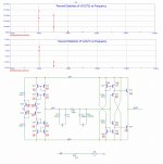
Y is in milli/micro percent. The top THD chart is for I/V + buffer, the bottom one is for I/V alone. There is some distortion cancellation happening, at least in the sim thus allowing us to get a better 2nd/3rd of the circuit. As i look at it... the first stage performs rather close to original 844 so it's doubtful whether the discrete will benefit from anything but low costness. The "double dot" bars are for 20c and 70c temperatures to see the temperature stability. The 20c is the lower "dot".
The THD could go lower on 15v/18v rails. A bit of current would do the same - but i have no clue how much current won't overheat the stuff. I have thermal compound ordered to cover the PCB + heatsinks + thermal matching of transistor pairs/whole circuit.
I hope to get away without degeneration resistors as i don't like 'em - they take too much space on the PCB - long traces, lots of EMI pickup.
Measured at 1kHz sine, 4mA swing (tda1541).
There should be a servo to keep everything in place and DC-coupled.
Thanks s3tup, they are good distortion figures still for zero feedback. Can you tell me what happens at low frequency (20hz-1000hz) if you did pot this, as it seems the distortion is rising quite quick to 2khz, if it contiunes to rise it could get quite high at low frequencies.
Cheers George
Cheers George
- Home
- Source & Line
- Digital Line Level
- Using the AD844 as an I/V