Leave all pin 6's float, never tie them together, if using an external buffer.
Only if you want to use the 844's buffers stacked, don't tie them directly together, they each need a series 100ohm isolating resistor on each leg then the other side of the resistor can be together and the output taken from there.
Cheers George
OK. First thing to do tonight. I turned on my DAC for run-in. I hope those AD844s aren't damaged or anything. Now, I need to find a way to isolate those pins.
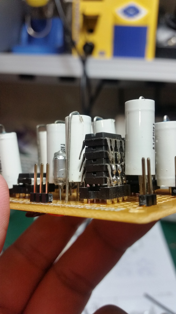
Stacking...
")
You need pin 5's tied together as well. Pin 6 should float or be through 100 Ohm series resistors. If you are going to try that output.Thanks for the warning. I will try to isolate those unnecessary pins tonight. I am not using pin6. Do I need to un-tie it also? As George has mentioned, pin 2,3,4,6,7 can be tied together. BTW, I didn't look into buffer OP yet. I tried single AD844 without problem, and then staked them for listening.
AD844's
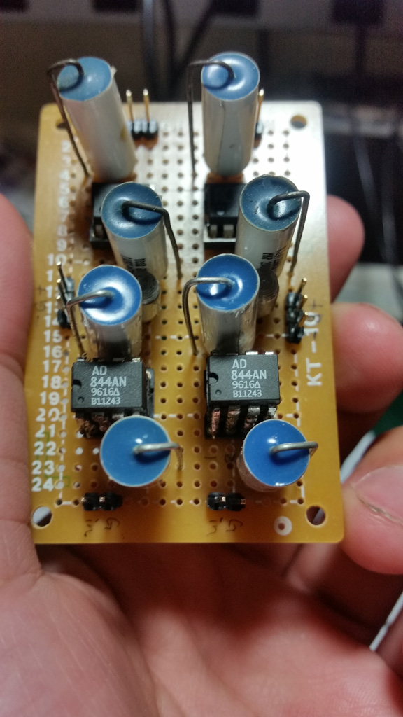
Post a picture. True AD844's are all AD (Analog Devices).Hi, I have some AD844s with different marking. one pair has AD logo two other pairs don't have logo. is it ok to stack them up?
AD844's
Are they running "HOT"? If not, they are likely OK.OK. First thing to do tonight. I turned on my DAC for run-in. I hope those AD844s aren't damaged or anything. Now, I need to find a way to isolate those pins.
Post a picture. True AD844's are all AD (Analog Devices).
One pair is in the photo in post #1381.
I have two other pairs that look like in this photo
https://lh3.googleusercontent.com/P1WEm2oJL3Hc8KPJRQtAWqbo6MBp7QxC6za_k6JrKrQ=w747-h561-no
Are they running "HOT"? If not, they are likely OK.
No, they are just fine. Maybe I was lucky. The stacked AD844s I have are having the same date code. (The other 4 are different, but still matched)
It turns out the easiest way to un-tie those pins is just to float them. I tried heat resist tape, duck tape...etc, but this is the best in my opinion. No one will open my DAC anyway. It should be safe.
AD844 Fakes...
Could be late production.... Here is the thing. I have some older ones and they have a softer dull labeling. I also have a few in Cerdip package. Only a true AD844 can be applied with the pin 5 TZ no negative feedback scenario. No other chip features that. Test each chip as a solo (not a stack). Make sure they work as a single pin 5 output. If they work they are real. I have not actually seen a fake AD844 to date. Doesn't mean they are not out there.One pair is in the photo in post #1381.
I have two other pairs that look like in this photo
https://lh3.googleusercontent.com/P1WEm2oJL3Hc8KPJRQtAWqbo6MBp7QxC6za_k6JrKrQ=w747-h561-no
Floating pins...
That should work fine. Put some hours on it and see what you think of the sound quality.No, they are just fine. Maybe I was lucky. The stacked AD844s I have are having the same date code. (The other 4 are different, but still matched)
It turns out the easiest way to un-tie those pins is just to float them. I tried heat resist tape, duck tape...etc, but this is the best in my opinion. No one will open my DAC anyway. It should be safe.
That should work fine. Put some hours on it and see what you think of the sound quality.
Hi,
I found not every unity gain OP is working properly after I/V. Most of them showed 10mv to 20mv (even 30mv for AD846) DC at the output (without input). And they usually sound a little bit harsh at HF (not obvious, but detectable). On the other hand, OPA134 works perfectly here which measured only 1~2mv. The sound of OPA134 is quite smooth and sweet (very stable?), but the fine detail is not as good as ADA4627. I think I need to have a properly designed PCB for this I/V+buffer stage. Breadboard solution may not offer optimal performance here.
Last edited:
Output Op amps
This of course is true. Not all unity gain devices like to see the RF hash from the I/V process. How bad it is will depend on that capacitor across the feedback resistor on Pin 5 TZ. Think of that as a first order filter. AD846 is a transimpedance amplifier and could be used as the I/V. Used those years ago. Nice sound however only 12 bit accurate as I recall. Still the sound was nice. Bread boarding... I have done a lot of that with good results. So a very dedicated PC board might offer you an advantage. To date I have experience with TDA1541,A and PCM1704's. I have not played with the AD1862's. So I don't know it's behavior. Share your findings if you build a dedicated board. I will be putting my effort into the Pedja DDNF for the PCM1704's just as soon as I am getting around a bit better. I really don't like having to use a walker.Hi,
I found not every unity gain OP is working properly after I/V. Most of them showed 10mv to 20mv (even 30mv for AD846) DC at the output (without input). And they usually sound a little bit harsh at HF (not obvious, but detectable). On the other hand, OPA134 works perfectly here which measured only 1~2mv. The sound of OPA134 is quite smooth and sweet (very stable?), but the fine detail is not as good as ADA4627. I think I need to have a properly designed PCB for this I/V+buffer stage. Breadboard solution may not offer optimal performance here.
Hi, do you still need a buffer after DDNF? I am planning to try different options, including discrete buffers. Or, at least, I have to find solutions to make OP working as stable as possible. The smooth sounding is quite important to me. BTW, this also reminds me that my OPA861I/V also has 10+ mv DC on the output. Maybe it wasn't fully working stable, either.
Last edited:
Pedja Rogic DDNF circuit boards
I think it is a good idea. The reason is as previously stated. 10 uF output cap will limit low end response unless your preamp is unusually high impedance. I want to preserve the low end and additionally a low value film and foil capacitor is far more affordable in the 0.1 uF range. Buffering also takes much of the load off the I/V stage. Important I think for low distortion. For the PCM1704 DAC I really hope to match enough devices to DC couple the output. That would avoid the low frequency roll off problem. In addition to the first order filter I often use a line transformer based passive filter using a Cinemag 600/600 transformer and a 4n7 Polystyrene capacitor. This avoids any additional active filter stage. This seems important in my Ribbon based loud speaker system.Hi, do you still need a buffer after DDNF? I am planning to try different options, including discrete buffers. Or, at least, I have to find solutions to make OP working as stable as possible. The smooth sounding is quite important to me. BTW, this also reminds me that my OPA861I/V also has 10+ mv DC on the output. Maybe it wasn't fully working stable, either.
I think it is a good idea. The reason is as previously stated. 10 uF output cap will limit low end response unless your preamp is unusually high impedance. I want to preserve the low end and additionally a low value film and foil capacitor is far more affordable in the 0.1 uF range. Buffering also takes much of the load off the I/V stage. Important I think for low distortion. For the PCM1704 DAC I really hope to match enough devices to DC couple the output. That would avoid the low frequency roll off problem. In addition to the first order filter I often use a line transformer based passive filter using a Cinemag 600/600 transformer and a 4n7 Polystyrene capacitor. This avoids any additional active filter stage. This seems important in my Ribbon based loud speaker system.
Hi,
I also prefer direct coupled. Good caps are usually overpriced. Some are even untouchable for me...
May I ask how you wire the transformer? I had a few, and perhaps give them a try. Do you still need the 4n7 cap for transformer? I thought the trafo is natively an effective LPF. Usually trafos also have large distortion at low end, could be worse than caps.
There is something I'd like to share. Speaking of the OP buffer, I thought the ADA4627 and Muses02 are good enough for this purpose until I tried the ADA4898-1 today. The ADA4898-1 is really really amazing here. It's fully stable with simple non-inverting setup @ G+1. The sound is crystal clear, very smooth, rich HF with good bass. Very impressive indeed. I think this is the one. It's hard to believe OP buffer can largely differ in audio performance. I strongly encourage you to try it.
Passive output stage filter
Hi canvas, Good caps... I agree with you. Even in the USA good caps cost far to much. The ideal situation is to only use them if you must. I like the Audio Cap Theta PPT's from Parts Express. Around $8 US Dollars for each piece. That is for the 0.1 uF value. Still very expensive although I have some NOS (new old stock) Teflon caps in that value that run $50 a piece these days. I still prefer the first cap. Cinemag filter.... You can also use Lundahls (!$!), Edcors or my favorite Cinemag transformers as a filter. Wire the primary with a series ~600 Ohm resistor. The 4n7 Cap will go across the primary winding. On the output winding place a ~600 Ohm resistor across the secondary. Wire to RCA on back panel. I'll have to check my files to see if I have a schematic to upload. As a picture helps. The cap with the inductance of the primary winding forms a second order roll off function. I have found no downside to using input transformers in this way. If you can hear RF rubbish in your DAC this will filter it. Some transformer like a 3n6 capacitor so measuring it with test tones and an oscilloscope is worth while. Output op amps... Not that familiar with the more modern ones. I will look into that. Thanks.Hi,
I also prefer direct coupled. Good caps are usually overpriced. Some are even untouchable for me...
May I ask how you wire the transformer? I had a few, and perhaps give them a try. Do you still need the 4n7 cap for transformer? I thought the trafo is natively an effective LPF. Usually trafos also have large distortion at low end, could be worse than caps.
There is something I'd like to share. Speaking of the OP buffer, I thought the ADA4627 and Muses02 are good enough for this purpose until I tried the ADA4898-1 today. The ADA4898-1 is really really amazing here. It's fully stable with simple non-inverting setup @ G+1. The sound is crystal clear, very smooth, rich HF with good bass. Very impressive indeed. I think this is the one. It's hard to believe OP buffer can largely differ in audio performance. I strongly encourage you to try it.
Simple second order passive filter
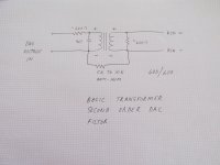
Hi canvas, Here is a simple schematic. Another nice thing about transformer based filters is it allows balanced to single ended conversion if needed. The 5K Ohm or 10 K Ohm resistor provides a path back to ground to reduce hum if it is encountered. Not a common issue. Hope that inspires you.
Hi canvas, Here is a simple schematic. Another nice thing about transformer based filters is it allows balanced to single ended conversion if needed. The 5K Ohm or 10 K Ohm resistor provides a path back to ground to reduce hum if it is encountered. Not a common issue. Hope that inspires you.
Attachments
Hi canvas, Here is a simple schematic. Another nice thing about transformer based filters is it allows balanced to single ended conversion if needed. The 5K Ohm or 10 K Ohm resistor provides a path back to ground to reduce hum if it is encountered. Not a common issue. Hope that inspires you.
Thanks for the schematics. It's helpful. As you mentioned, it's a filter. I assume you are passing the signal to a preamp? I do not have a preamp. Should I put the trafo between AD844 and the buffer?
Filter....
I use that right behind the buffer. So it does go between the DAC and preamp. However depending on your setup you could place it between an I/V and the Buffer. Input and output impedance is about 600 Ohms. So the load is fairly light. Can also be useful in situations where you have excessive RF hash. Typically it rolls off at 19-20 Khz at a second order rate. Usually quite adequate for most DAC applications. Avoid placing high idle currents through the transformers. They work best with no more then a few mV's. I have used the cheap Edcors in this schematic and they work well. Lundahl LL1690's like 4n7 changed to 3n6 for the same roll off.Thanks for the schematics. It's helpful. As you mentioned, it's a filter. I assume you are passing the signal to a preamp? I do not have a preamp. Should I put the trafo between AD844 and the buffer?
Trafo's...
The transformer filter would work off the AD844's Pin 6 output. It is not high enough to do any thing around Pin 5. That is a special case. Burn in.... If the change is large then something odd is going on. Picking up noise or something. You need to get a handle on that. Are you in a RF noisy environment? Lots of things can be noise sources. Florescent lighting is a broad band noise source for example. Other ideas.... DC power supplies stable? Local heating of the IC chips?I will try the trafo definitely. Back to the ADA4898-1, it turns out my circuit is not 100% stable after 20+ hours of burn-in. I don't know what has happened. Both channel shows different amount of DC at output. They were under few mv before run-in. Very strange...
- Home
- Source & Line
- Digital Line Level
- Using the AD844 as an I/V