") . the tube is maybe a pentode , the linearity of the tube parasite capacitance permit the excellent linearity at 1Mhz.
. the tube is maybe a pentode , the linearity of the tube parasite capacitance permit the excellent linearity at 1Mhz.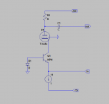
Inspired by this thread I have replaced my common base AD844 output stage with Pedja's discrete version. With the TDA1541A I'm using it without a buffer as I prefer the improved transparency as I did with the AD844 with its output directly from pin 5. I have tried two versions, one using BC550/560 and the other with 2SA970/2SC2240, all selected for highest gain but not matched. Well worth the effort! The BC version is very dynamic and highly focussed, not kind to bad recordings but far ahead of the AD844 overall. The 2SC version is more laid back and is an easier listen, very refined, and is very open and delicate in the treble. Very happily living with this now.
Best cap is no cap. As good as circuits can be, they are ruined by the colouration of cap coupling.
Very simple though, is this it (Terry) Zenelectro?
Cheers George
Apologies - have been away.
There are a few ways to do it they all work, however the type of
components, voltages, currents, noise gains of CCS make the big difference.
Some of this shows up on sims some doesn't.
The same rules apply to the diamond I-V and this is why I dislike the 844,
you cant change the devices or currents. They are just a 'dumb' solution.
There is a further development which involves a distortion cancelling single
discrete semi that brings the simulations down to -140dB depending on DAC
but I've yet to try this in real life. It should work.
I'd build these up if there were enough interested but ATM there are some
other projects in front.
WRT caps versus no caps - the best systems I've ever heard had caps
in the signal path. Changing a circuit for the worse to negate a cap is, IMO,
folly. The only downside is you need to use good ones = can be expensive,
depends how you implement it.
Again, if you think a bit laterally there are much better ways to implement
the cap pre OP buffer which bring the cap signature down to very small
levels.
Thanks go out to Pedja/Georgehifi for this great idea. First I must say that I have only tried a single AD844 with internal buffer per channel in a sub-par layout. With oscillation, only three pin regulator +-12 volts, and the AD844 in a socket that had a dual IV opamp it sounds better that any other opamp system I have had. The greatest gain in my system was in the sound stage, which is projected across the front wall like never before. I have also noted that there is now greater low level detail, and better decay. I guess I discovered what the rest of my system sounds like. I am now in the process of removing the sockets and improving the decoupling. I would like some direction as to how to ground this chip. The board layout has a top ground plane under the chip and the ground track for the power supply running on the under side of the board. Pin 3 connects to both(thru a pin hole/via) and Pin 5 connect to the top board plane and to a small plane under the board(thru a pin hole/via). My thought was to connect pin 5 thru a resistor/cap to this top plane and connect pin 3 to both thru the pin hole(via). The output would go to the RCA jack from pin 1 and the top ground plane. The data sheet says the decouple caps should be taken to a point close to the load(or output connector). Should the decouple caps connect to the chip pins and the top ground plane(putting it close to the output connection), thus making the power supply ground contact thru pin 3 or should they be connected on the underside of the board to the ground trace(pin 3) and pins 4/7? Is there any difference? Maybe neither is optimal, but that is what I have to work with............For what it's worth, I have only one cap in the signal path, and would like to keep it that way.....
Thanks go out to Pedja/Georgehifi for this great idea. First I must say that I have only tried a single AD844 with internal buffer per channel in a sub-par layout. With oscillation, only three pin regulator +-12 volts, and the AD844 in a socket that had a dual IV opamp it sounds better that any other opamp system I have had. The greatest gain in my system was in the sound stage, which is projected across the front wall like never before. I have also noted that there is now greater low level detail, and better decay. I guess I discovered what the rest of my system sounds like. I am now in the process of removing the sockets and improving the decoupling. I would like some direction as to how to ground this chip. The board layout has a top ground plane under the chip and the ground track for the power supply running on the under side of the board. Pin 3 connects to both(thru a pin hole/via) and Pin 5 connect to the top board plane and to a small plane under the board(thru a pin hole/via). My thought was to connect pin 5 thru a resistor/cap to this top plane and connect pin 3 to both thru the pin hole(via). The output would go to the RCA jack from pin 1 and the top ground plane. The data sheet says the decouple caps should be taken to a point close to the load(or output connector). Should the decouple caps connect to the chip pins and the top ground plane(putting it close to the output connection), thus making the power supply ground contact thru pin 3 or should they be connected on the underside of the board to the ground trace(pin 3) and pins 4/7? Is there any difference? Maybe neither is optimal, but that is what I have to work with............For what it's worth, I have only one cap in the signal path, and would like to keep it that way.....
Hi optimationman, indeed it does sound far better than any opamp with feedback based way of doing I/V.
As for grounding the TZ point resistor, the way mine was done on two identical cdp's now was to use the same ground point that the old opamp i/v (opa627) used for it's pin 3 which is the analog ground plane.
As for the power +&- supply rails I was fortunate that the rails (+- 15v) for the the OPA627 were well regulated nice and smooth, and I just used them instead.
BTW what dac is your unit using, I I found that two 844's stacked per channel was a magintude better again even when using the low ouput PCM1704K dac's, and my friend has the same CDP and he says after I did it it's even better with 4 stacked, we have yet to do a direct A/B 2 vs 4 yet, maybe next week.
PS just noticed you are using PCM1704, definately do 2 stack, or even 4 as my friend love 4 and Sergio's sims back that up as well.
Cheers George
Last edited:
HI Georgehifi, I have a factory board to work with so that is fixed. They used a dual opamp, but only one side(shorted out the other?)thus a difficult pin configuration to work with(dual vs single pin layout). I had to make some other changes because the original layout was differential PCM1704's(2 per channel) to only one per channel(long story). I was lucky enough to have really no offset on the two PCMs and less than 8mv offset with one AD844. I tried a quick but dirty mod just to see if it was really what I wanted, even the two up AD844s. However this dual arrangement upset the offset and I got 80mv on one and -22.4mv on the other. So I will go back to just one for now and try to figure a way to take care of the offset. Not to easy on this board as the PCM1704s are surrounded by silmic caps in close and no real access to them!
HI Georgehifi, I have a factory board to work with so that is fixed. They used a dual opamp, but only one side(shorted out the other?)thus a difficult pin configuration to work with(dual vs single pin layout). I had to make some other changes because the original layout was differential PCM1704's(2 per channel) to only one per channel(long story). I was lucky enough to have really no offset on the two PCMs and less than 8mv offset with one AD844. I tried a quick but dirty mod just to see if it was really what I wanted, even the two up AD844s. However this dual arrangement upset the offset and I got 80mv on one and -22.4mv on the other. So I will go back to just one for now and try to figure a way to take care of the offset. Not to easy on this board as the PCM1704s are surrounded by silmic caps in close and no real access to them!
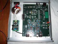
What a PCM1704 Evaluation Board from BB!!! nice never seen one post a pic of it.
Cheeers George

This badboy?

View attachment DEM-PCM1704 eval fixture mXxsvtu.pdf
View attachment user guide sbau013.pdf
Last edited:
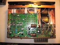
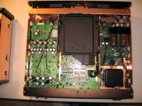
I just noticed that the nulling circuit Georgehifi used connects to the AD844 not the PCM1704, so I will do this to zero out the output. I also believe that no cap is best. I will post a picture of the dac layout in the Denon 5000. The Denon 9000 is similar in the dac layouts as I have both. Previous owners sold them as they thought the lasers were bad. Turns out the 5000 needed only realignment and the 9000 lost it's clamping magnet. So both work fine now.
- Home
- Source & Line
- Digital Line Level
- Using the AD844 as an I/V