Hi Jeff, wondering if your up to it some more simming, my current tz resistor is 4.7k with 350pf then from TZ into the discrete buffer circuit, more gain again with this setup, your sim should show this.
But I was wondering a 15k and 100pf TZ then into the discrete buffer, what the sim would show up as far as the gain comparison, can it do distortions as well?
Cheers George
But I was wondering a 15k and 100pf TZ then into the discrete buffer, what the sim would show up as far as the gain comparison, can it do distortions as well?
Cheers George
Last edited:
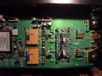
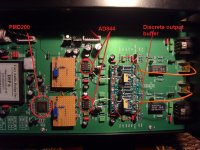
Hi Ken it's the Cary CD 303-200 and it comes with digital domain volume, switchable PMD200 hdcd, and I believe a DF1704 under the covers?(pic attached).
Cheers George
Okay, I see. The module in the photo labeled DSP 6 probably contains a DSP chip performing the digital filtering (PMD200) in software, and also implements the digital volume control.
I'm confused about something. Stupidity on my part here, but are the PCM1704 to which you've been referring part of the original Cary player design, or re they part of some external DAC box? If they are a part of the Cary player, are you transmitting their current output signals to some added AD844 board, or are the AD844s also part of the original player?
Last edited:
George:
To my understanding, the PMD200 was never an actual hardwired chip, like was the PMD100. The 'PMD200' only existed in software as a product. Since Microsoft purchased Pacific Microsonics way back when, I shouldn't be surprised if there is a version ported to Windows PCs. It definitely was ported to DSP ICs as firmware. I believe that the only hardwired (ASIC) HDCD chip was the PMD100. However, I'm open to correction on that.
To my understanding, the PMD200 was never an actual hardwired chip, like was the PMD100. The 'PMD200' only existed in software as a product. Since Microsoft purchased Pacific Microsonics way back when, I shouldn't be surprised if there is a version ported to Windows PCs. It definitely was ported to DSP ICs as firmware. I believe that the only hardwired (ASIC) HDCD chip was the PMD100. However, I'm open to correction on that.
They are still around, but they will cost you.
PMD200 HDCD Decoder IC from Pacific Microsonics | eBay
Cheers George
PMD200 HDCD Decoder IC from Pacific Microsonics | eBay
Cheers George

Isn't that exactly what a PMD200 is? A DSP56300 re-badged by PM?
That would comport with what I had always thought, if that is indeed a DSP chip inside the package of that pictured IC. What I didn't realize was that PM had sourced their own brand labeled DSP devices with their HDCD algorithms hard coded on-chip in (P)ROM. I had been under the impression that users were required to directly source the DSP IC from the semiconductor vendor, then license the HDCD code separately from PM, and then integrate the two themselves. I'm not sure how I came by that notion.

Based on those mistaken reasons, I had not been surprised that the PMD200 seemed to be a market failure, relative to the PMD100, despite the technology it embodied. So, then, does anyone know why the PMD200 had nowhere near the market success of the PMD100?
Last edited:
There was someone on the net that had a moded Audio Alchemy DDE V3 I think it was, and he did a/b's with plugin cards that had the DF1704, PMD100 and PMD200 and sonicly he said the df1704 was trounced by the PMD100 and then it was beaten again by a smaller margin by the PMD200. (I'll see if I can find the link again)
Found it http://www.jeffchan.com/audio/filter-comparison.html
Cheers George
Found it http://www.jeffchan.com/audio/filter-comparison.html
Cheers George
Last edited:
Just bought the SQ and dynamics up some more. After doing a lot of searching it seems that the TZ output in non feedabck mode has an output impedance of 3mohm!!!
My buffer if you look at the circuit I posted has a input 100k R6 to deck, I removed this and got a couple db more overhaul gain, and then for good measure removed C2 as well, because with this high output impedance of the TZ who knows how this is filtering, it lifted the 20khz roll off from about -1db to now about -.5db. All these mesasurments are taken from the ouput of the buffer.
Sound you ask?? well now it's hypnotic, sublime, doesn't even sound like it's comming from the speakers at all you just want to turn it up and up to ridiculous levels with no strain.
I double checked there are no oscilation from the buffer even when it's input is open circuit. Would anyone know what the input impedance is now of the buffer with just the fets seen by the TZ??
Cheers George
Last edited:
Forever the fidler guys, is it possible to straight stack these AD844's the way I am using it, with no feedback and signal from the TZ?
As I would like to know what the sound difference will be with the input reduced from 30ohm to 15ohm.
I would probably have to play with the TZ resistor to get the gain the same as a single.
Cheers George
As I would like to know what the sound difference will be with the input reduced from 30ohm to 15ohm.
I would probably have to play with the TZ resistor to get the gain the same as a single.
Cheers George
Ok, no one has the cojones to help/advise me blow up some stacked AD844's, so I gritted my teeth and went for it in my usual blind but methodical method.
Here's what I did, stacked another AD844 on top of what I had only soldering together
pins 2 3 4 5 & 7 crossed my fingers and hoped nothing would fry. (all safe!!!) I did not parallel pin 6 1 & 8 as I don't use the inbuilt buffer or the null pins, and though not to temp fate.
Measurments were: Abraxalito's dac dc offset adjustment had to be readjusted a little to zero the dc at the TZ point again and remained nicely stable still at + & - .1mV so good so far.
Then I checked the output level and to my supprise it was the same, as I thought that now with 15ohm input impedance instead of 30ohm, the TZ output would be half of what I had before, anyone have an explaination for this?
Now for how it sounds, (you guys have to stack these for the PCM1704/2) as the first thing that struck me was it was even more punchier in dynamics the bass was even tighter and everything was even cleaner.
I don't know if the big improvements were because of the 15ohm dac loading now compared to 30ohms or the TZ output has changed character, not in level but impedance or current delivery. Or that maybe the dacs output was too much for the input of the single I/V as now it's being shared by the two AD844's.
What ever it is, this stacking has to be done, as one 844 is clearly not doing it as easy as two.
This now makes me think what would quad stacked (7ohms) ones sound like?
Cheers George
Last edited:
s3tup, you seemed to have done quite a bit of playing around with this as your discrete knock off shows.
It's been said that the TZ output impedance is 3mohm in non feedback mode as I'm using it as a single, what happens to it now that it's stacked, does it halve like the input impedance and become 1.5mohm?
Because stacking them is a big change and the dac (pcm1704) is only +- 1.2mA output and that should not overload a single AD844 input as some are using TDA1541's into it and they are 4mA.? Or is it the input impedance is now halved that's making such a big change to SQ.?
Cheers George
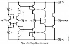
The output impedance of TZ node is kinda weird as nonexistent, it's current source with the current set by the inverting input current, it just gives you a possibilty to connect larger resistor for i/v without stucking into voltage compliance of DAC output...
I'd guess the actual output impedance should be the same as the I/V resistor used, but it's kinda weird as any extra load you put on the TZ output becomes a part of I/V conversion (so any nonliniarities here are not welcome at all).
When you connect 'em in paralel, you both halve the input impedance (which is good - the farther away we are off DAC's voltage compliance the better)
And,
The transistors inside the 844 are a bit current starved, and you don't have access to their bias network... So they distort a bit with larger current swing. If we use a pair of 844, we halve the max current thru each of 844's and stay in more linear region of transistors, hence lowered distortion.
You may try to pump the voltage a bit towards 15v max spec, this way the current will (should) rise and 844 should tolerate larger current swings. But be carefull not to overheat them, heatsinking may help.
It's surprising you've got better results with 1702/4 DACs as they have rather weak output. More powerful DACs as 1541 will benefit more from multiplies of 844.
Thank's for that great explaination on this oddball opamp.
Yes I was surprised also at the huge improvement with two over one, and I thought the one sounded incredible.
As you I thought the 1704 would not trouble it at all with just +- 1.2mA output, but clearly even this was too much for the AD844, I do run a 4.7kohm TZ resistor though could this be the reason?
Cheers George
I'm so impressed with what the double stack 844's have done with the PCM1704's , I just ordered 4 more to go quad for each channel.
I got them from HK so I'm hoping they are originals, it would be hard to fake these as nothing else has the pin 5 TZ output to fake them with.
If I static measure with a DMM from pin 5 to pin 7 or 4 (+ & - Vin), what if anything should it read going through two transistors? Just to check before the soldering starts?
Cheers George
Attachments
- Home
- Source & Line
- Digital Line Level
- Using the AD844 as an I/V