I think that tda1541a has a midrange magic that can't be matched by any other dac chip. However it's treble and bass are a bit soft. Therefore a very good i/v stage would mitigate these limitations and would bring its bass and treble performance closer to the level of its midrange.
BB top r2r DACs have good performance across the whole range. The sound is very nice and detailed but does not have the magic factor in the mid as the tda1541a. That why I think tda1541a has its own nice color.
BB top r2r DACs have good performance across the whole range. The sound is very nice and detailed but does not have the magic factor in the mid as the tda1541a. That why I think tda1541a has its own nice color.
I have built a few instances of a classA CFB circuit, I'll see if I can find the schematic.
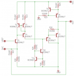
Thanks go to Matt Garman who drew up this schematic based on my scribbled drawing. I haven't put in the resistor values as some of them will be dependent on which DAC you decide to connect it to. Happy to work them out for anyone who decides to go ahead and build this.
Its a current-feedback amp and the I/V resistor is R27. You can choose whatever output voltage you need by fixing this resistor appropriately.
As drawn its fairly basic and suffers from some DC instability which could be fixed by addition of an opamp servo. Not that I've tried it as I've been happy on my DACs to use capacitor coupling of the output.
Attachments
I/V resistor
For a parallel summed TDA1541A the value of 25 Ohms is about ideal as far as compliance goes. A single TDA should be about 47 Ohms. These are non standard values so I use a quality metal film in parallel. I read the ideal value for a PCM1704 is 10 Ohms however I have not tried it. This is on the grid of the tube in all cases. I actually have the 10 Ohm Rhopoint resistors on hand.") Practical standard values are 10, 30 and 50 Ohms in the Rhopoint catalog. Expensive.... However worth it.
Practical standard values are 10, 30 and 50 Ohms in the Rhopoint catalog. Expensive.... However worth it.
Rhopoint I/V resistor
What value is this?
Cheers George
For a parallel summed TDA1541A the value of 25 Ohms is about ideal as far as compliance goes. A single TDA should be about 47 Ohms. These are non standard values so I use a quality metal film in parallel. I read the ideal value for a PCM1704 is 10 Ohms however I have not tried it. This is on the grid of the tube in all cases. I actually have the 10 Ohm Rhopoint resistors on hand.
Practical standard values are 10, 30 and 50 Ohms in the Rhopoint catalog. Expensive.... However worth it.I2S Fifo...
No... I should look into that.Have you tried IanCanada's I2S FIFO? If not, this could be a huge improvement over traditional digital receiver/filter. IMHO, it's a game changer in audio diy world.
For a parallel summed TDA1541A the value of 25 Ohms is about ideal as far as compliance goes. A single TDA should be about 47 Ohms.
Do you need to give the output stage much gain to get to 2v or more output?
Cheers George
My own experience was that high gain stage after the passive i/v compromises noise performance. I used an srpp stage with 1950s siemens ecc88 tube. The tone was nice but resolution was limited if compared to a good active i/v.
Could it be that my tube gain stage is not good enough? But I think any high gain stage amplifies both signal and noise proportionally.
Could it be that my tube gain stage is not good enough? But I think any high gain stage amplifies both signal and noise proportionally.
Last edited:
My own experience was that high gain stage after the passive i/v compromises noise performance. I used an srpp stage with 1950s siemens ecc88 tube. The tone was nice but resolution was limited if compared to a good active i/v.
Could it be that my tube gain stage is not good enough? But I think any high gain stage amplifies both signal and noise proportionally.
This is why I asked what the gain was after the I/V resistor.
As with you I've experienced way too much noise increase after an I/V resistor to get anywhere near a 2v output, because of the amount of gain needed, and the sound suffered because of it. Can't beat a good low input impedance active I/V that why stacking the 844 to x3 gives around 10ohm input impedance which current output dacs love to see, without a noise penalty.
Cheers George
Last edited:
I got the schem made for me a few years back(tube/jfet stage) by a tube guru here in Sweden. I have since lost touch with him and can't get his ok to share the schem.
As Dave is a friend I shared it privately with him.
However gain etc would be fine to share.
I write this as I have the deepest respect for the designer and his vast knowledge. I would not want to go against his wishes. He may be fine with sharing the circuit, but he may not be as well.
As Dave is a friend I shared it privately with him.
However gain etc would be fine to share.
I write this as I have the deepest respect for the designer and his vast knowledge. I would not want to go against his wishes. He may be fine with sharing the circuit, but he may not be as well.
My own experience was that high gain stage after the passive i/v compromises noise performance. I used an srpp stage with 1950s siemens ecc88 tube. The tone was nice but resolution was limited if compared to a good active i/v.
It compromises subjective performance (not measured noise though) because the DAC has a finite output impedance and hence feeds some noise from the power supply through to the output. This PSU noise feed-through is minimized in an active stage which presents the lowest possible input impedance to the DAC.
I reckon the lower the DAC's output impedance the more susceptible it is to PSU noise hence the more compromised its output is in passive I/V. Burr-Brown audio DACs tend to have Zouts in the hundreds of ohms upto 1k or so.
It Is well known fact that digital filter used with TDA1541A Is weak part
but PCM63, PCM1704 does use much better digital filters NPC5842 / 43 etc
but PCM63, PCM1704 does use much better digital filters NPC5842 / 43 etc
Have you tried IanCanada's I2S FIFO? If not, this could be a huge improvement over traditional digital receiver/filter. IMHO, it's a game changer in audio diy world.
Last edited:
SRPP
Hi George, No. I decided not to add a buffer on the output. It is quite close to CD standard output. The sound is as detailed as PCM1704 DAC. In fact it has a quality in the treble that I prefer. Imaging is different. Deeper sound stage more layered. Bass has drive... More then I expected. As Mayday pointed out I am not authorized to share the circuit sadly. Out of respect for the designer.
Do you need to give the output stage much gain to get to 2v or more output?
Cheers George
Hi George, No. I decided not to add a buffer on the output. It is quite close to CD standard output. The sound is as detailed as PCM1704 DAC. In fact it has a quality in the treble that I prefer. Imaging is different. Deeper sound stage more layered. Bass has drive... More then I expected. As Mayday pointed out I am not authorized to share the circuit sadly. Out of respect for the designer.
Hi George, No. I decided not to add a buffer on the output. It is quite close to CD standard output. The sound is as detailed as PCM1704 DAC. In fact it has a quality in the treble that I prefer. Imaging is different. Deeper sound stage more layered. Bass has drive... More then I expected. As Mayday pointed out I am not authorized to share the circuit sadly. Out of respect for the designer.
i'm happy you like how it sounds
How knows, the designer might not care at all, but since I can't ask...
Are you using the board I sent? Any difference from perf board?
I don't expect there to be much of a difference in SQ in that type of design though.
I think what George means is the signal voltage developed across the i/v resistor of 25 ohm is very small so any circuit that you used have to be a high gain one to provide usable output for any amp.
Yes this is correct, even if it's external, which would have even more noise to deal with.
Cheers George
Noise...
Hi George, I did some snooping and there is mild hum on the high gain setting on the headphone amp with volume at max. It is quite acceptable although I may be able to reduce it once it is installed in a chassis. Thing to remember is this would be well below CD redbook at greater than 96 db down. At this level playing music would blow your ears out on headphones. The 25 Ohm resistor has a signal of 0-8 mA's, as the DAC's are in parallel. So has roughly the same signal as a single 1541 on a 47 Ohm I/V resistor.
Yes this is correct, even if it's external, which would have even more noise to deal with.
Cheers George
Hi George, I did some snooping and there is mild hum on the high gain setting on the headphone amp with volume at max. It is quite acceptable although I may be able to reduce it once it is installed in a chassis. Thing to remember is this would be well below CD redbook at greater than 96 db down. At this level playing music would blow your ears out on headphones. The 25 Ohm resistor has a signal of 0-8 mA's, as the DAC's are in parallel. So has roughly the same signal as a single 1541 on a 47 Ohm I/V resistor.
SRPP
Hi Mayday, I am using my perfboard build for this one as it has the resistor values for the parallel dac's. I will test your board before getting the Mark 3 dac in it's new chassis. Your board has 47 Ohm I/V resistors so I will test it with just one of the Red Baron boards.
i'm happy you like how it sounds
How knows, the designer might not care at all, but since I can't ask...
Are you using the board I sent? Any difference from perf board?
I don't expect there to be much of a difference in SQ in that type of design though.
Hi Mayday, I am using my perfboard build for this one as it has the resistor values for the parallel dac's. I will test your board before getting the Mark 3 dac in it's new chassis.
Your board has 47 Ohm I/V resistors so I will test it with just one of the Red Baron boards.Gain on the SRPP...
Well the math goes something like this. We know the resistance is 25 Ohms (I/V resistor) and the maximum current for a parallel connected TDA1541A is 0-8 mA's. 0-4 mA's times 2. So the math says maximum voltage across the 25 Ohm resistor is 0.2 Volts. So if the SRPP stage has a gain of 10X. We are at 2.0 Volts. Don't know if we can say that is RMS. Although my guess is that it is. Having played with the parallel dac concept... I came to the following conclusion. It is better to sum the currents then to run the dac's through their own respective I/V's and then to just add them at the buffer as two voltages. It works to sum them at the buffer however all that happens is averaging. There is no gain to doing that otherwise. If I missed something here please let me know. Trouble is I never found a active device that liked having 0-8 mA's injected into them in a standard I/V configuration. So the reason for the resistor I/V and SRPP.
Do you need to give the output stage much gain to get to 2v or more output?
Cheers George
Well the math goes something like this. We know the resistance is 25 Ohms (I/V resistor) and the maximum current for a parallel connected TDA1541A is 0-8 mA's. 0-4 mA's times 2. So the math says maximum voltage across the 25 Ohm resistor is 0.2 Volts. So if the SRPP stage has a gain of 10X. We are at 2.0 Volts. Don't know if we can say that is RMS. Although my guess is that it is. Having played with the parallel dac concept... I came to the following conclusion. It is better to sum the currents then to run the dac's through their own respective I/V's and then to just add them at the buffer as two voltages. It works to sum them at the buffer however all that happens is averaging. There is no gain to doing that otherwise. If I missed something here please let me know.
Trouble is I never found a active device that liked having 0-8 mA's injected into them in a standard I/V configuration. So the reason for the resistor I/V and SRPP.I think the standard i/v resistor according to datasheet is 1k8. If you you 2 chips in prallel then 900 ohm would give the same voltage. If you divide 900 by 25 the required gain is about 36 times.
With active i/v, I believ one chip is better than parallel. There are many i/v stages that can accommodate 4mA incuding the one we discuss in this thread. With triple stacked ad844s and one tda1541 I got excellent dynamic sound.
Parallel chips is useful for passive i/v though.
With active i/v, I believ one chip is better than parallel. There are many i/v stages that can accommodate 4mA incuding the one we discuss in this thread. With triple stacked ad844s and one tda1541 I got excellent dynamic sound.
Parallel chips is useful for passive i/v though.
The TDA1541's output impedance is 3kohm at 4mA
My friend who had just an I/V resistor with it of 15ohms and a buffer to bring up the output to 1.5v, had way too much noise, as bad as listening to cassette tape hiss, and his pre and power were very quite Naims.
Cheers George
My friend who had just an I/V resistor with it of 15ohms and a buffer to bring up the output to 1.5v, had way too much noise, as bad as listening to cassette tape hiss, and his pre and power were very quite Naims.
Cheers George
- Home
- Source & Line
- Digital Line Level
- Using the AD844 as an I/V