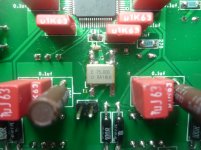
I meant IV opamps, 6 LME49990s. I've build two boards, both have the same heat problem. What may cause that?
Worst are the last two opamps, they reach ~90-100 degrees Celcius. I have changed power supplies, built multi-stage regulated supply with independent Salas LV regulators for analog, digital, and IV stages, noisewise they are very clean and voltages are not exceeding the standards; 3.3V for digital, 3.45V for analog, and 12.2V for IV. I'm seriously puzzled.
How about current load ?
Wondering ...
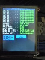
having an epson x-tal of 75 MHz and feeding my DIYINHK via an Amanero I've played my 1st 384 track just to see if it would lock on to it and play in the end and YES ... it locked, loaded and played instantly although at the end of the track it started to generate a lot of digital noise but that disappeared and stayed away as soon as another track started to play/stop.
I got the impression those higher rates (here 18432 kbps, 384000 Hz in foobar) were only possible with a 100 MHz clock ... seems it works with 75 MHz as well ... and sounds really good as well ...
Attachments
I have a question: I bought old version AVCC and Trident regulators from TPA. I did not separate AVCCL and AVCCR as I am a newbie and I want to make sure the board works fine with default configuration. While AVCC regulator has two output but the board has one AVCC input, could you advise how should I wire AVCC regulator to the board? By using only one output or bridging the two outputs?
None replies but I have another question. If I cut the trace on my rev5 board, I can use CN8 as AVCC_R. I saw only one voltage divider (10k/10k), does it mean only one channel's offset will be used for both channel? Schematic has two voltage dividers for Offset_L and Offset_R
I ordered the wrong resistors for the second time now. The first time I selected 1/4 watt on mouser but you are still able to order 1/2 parts. I learned from my mistakes I tried again. But again I *!@#$% up. I now have 1/4 watt dale resistors but again the wrong format. They are 71-RN65 parts and they are too big. I used them anyway but it really doesn't look nice.
Why don't you stay in the RN61 range then? well a lot of them were not available so I bought the more expensive ones.
What would you do? leave them or spend another 20 euro's shipping + parts and try again?

Why don't you stay in the RN61 range then? well a lot of them were not available so I bought the more expensive ones.
What would you do? leave them or spend another 20 euro's shipping + parts and try again?
Probably a stupid question but everyone seems to be using electrolytics for the 10uF power supply decoupling for the op-amp positive and negative supplies. I was thinking of using SMD X7R's in these positions. Are these suitable for these positions or do the caps here need to be polar like electrolytics?
I have completed building the two boards to create a dual mono set-up. One board works great (and sounds very good) but the second one is showing a short circuit on the 3.3V AVCC supplies. I suspect it is either the Sabre chip or the board but I am in the process of removing all of the AVCC capacitors just in case one of them is shorted to earth to be sure. Any ideas appreciated.
I use LC filtering before my AD811 I/V stage. Have you tried an 811 as an I/V?
I am keen to explore whether slew rate/settling time is more important than pure noise considerations for IV and wanted to use this op amp for its very good performance in these areas.
Would I need to amend any component values around the IV op amps to use the AD811 due to its CFB architecture or is it just plug and play?
To answer my own question with regard to the AD811, I tried these as a straight swop in this design and they started to oscillate and get very hot. Solution is a 1K resistor in series with Pin 2 of the Opamp as recommned by Walt Jung to get stability. Tried this and the Op amp is stable and works very well
To those who manage to get a lock with Epson Saw 75MHZ oscillator, my build only manages 96khz and doesn't lock into a 192khz signal let alone the 300's. I don't have any termination resistors but am using a ribbon cable from the Amanero with ground conductors adjacent the signal.
If the issue is termination resistors, where have you installed these as there is no space allocated on the board for these.
Any other suggestions appreciated.
If the issue is termination resistors, where have you installed these as there is no space allocated on the board for these.
Any other suggestions appreciated.
my board is using an Amanero with no resistors just some very short flat cables (appx. 2.5 cm) and DOES lock on to anything I have as a S/R. that is ranging from 44.1 to 384 and even DSD 2.8 / DSD 5.6.
It is recommended to keep the wires as short as possible ....
It is recommended to keep the wires as short as possible ....
Attachments
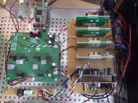
... using a epson saw 75 MHz as well ...
Plus, having a separate PSU for the A/V opamps, AD797 from transformator to super regulator for +12.41 and -12.40 V with 4x4700 uF in the rectifier units. As a super regulator I have chosen the SSR01 and SSR02 from Sjoestrom Audio.
Plus, a separate PSU for the digital part, again from transformator to the TI regulator TPS7A4700, using again 4x4700uF in the rectifier unit.
And modified the DAC board to separate the Left and right analog section to be able to supply again separated PSU units for left and right to the analog parts in the chip.
I have still a separate PSU channel unused, this is for a future expansion to separate the Amanero from computer USB. Plus for an MCU controlling the DAC chip using I2C and taking commands through BLE .....
I believe how well this board will behave is proportional with how clean your power supply and your assembly layout are. I have had very good results with Salas LV regulators(3x3.3v and a +/- 12v) after 2 LT1764 based pre-regulators. Similarly I used 3 TPS7A4700s with equal success. Your cables should be tightly twisted, flat cable to Amenero (or Diyinhk's) be at most 10-12cm.To those who manage to get a lock with Epson Saw 75MHZ oscillator, my build only manages 96khz and doesn't lock into a 192khz signal let alone the 300's. I don't have any termination resistors but am using a ribbon cable from the Amanero with ground conductors adjacent the signal.
If the issue is termination resistors, where have you installed these as there is no space allocated on the board for these.
Any other suggestions appreciated.
I tried several opamps, and settled with all LME49713HAs. They exceptionally satisfy my taste..
Thanks Guys. I use Jung type super regulators (ALWSR's) in conjunction with TPS7A4700 for both DVCC and AVCC so it is a superclean supply. I can't see this being the issue with my locking problem. The I2S connections are 10cm ribbon cables with parallel earths so pretty clean in theory. Could it be that my Epson Saw 75MHZ has been damaged during soldering (too high a heat?). I have not connected a Arduino to this so the DPLL bandwidth settings are the default values. From the pictures there are no controllers in the set-ups you have so using default DPLL bandwidth settings too?
Any ideas as to what I might try to solve?
In terms of OPamps, I have tried LMM49710's, even better performing LME49990's and the CFB Walt Jung recommended AD811's. The LME49990's seem to provide the greatest clarity.
Having looked at the datasheet for LME49713's, they seem to have an outstanding output current capability (+-100mA) and slew rate (1900V/uS) with excellent (but not class leading) noise and distortion performance. It is also a CFB design so needs a 1.2k resistor on Pin 2 for stability? My own hunch is that high output current (driving ability) and slew rate are more important than outright noise and distortion which is most probably in the inaudible range already. Have you tried the LME49990's and compared these against the LME49713's?
Last edited:
- Status
- Not open for further replies.
- Home
- Source & Line
- Digital Line Level
- Build thread for Diyinhk ES9018 DAC on Ebay