Electrolytic cap polarity....on the board.....
1) What are the polarities for the two 10uf caps to the right and left the 9018 chip ? (when looking at the chip/board printed side up)
I'm assuming these are bypasses for the two +3.3v psu's....so, negative to ground, for both...correct ?
2) I am also assuming the 10uf cap immediately above the chip is also a bypass for the +1.2v regulator....so negative to ground there too. (?)
~~~~
I've figured out the cap polarities for the opamps...
Positive power pins..... (-) to ground.
Negative power pins.....(+) to ground.
I'm using some SMT package 16v/10uf electros' that will fit everywhere (4 mm Dia. x 5.8 mm L x 5.5 mm H)....even next to the 9018 chip. >>>>except for the ADP151 regulator, where ceramics are specified by the manufacturer.
Here are the electrolytics (low ESR) I'm using...... Type AFK
Last edited:
Let me try this again.
This is my first venture into digital. I am just a hobbyist.
This is my first DAC project. I realize most of you have built several.
Remember your first DAC venture ?
So I'm asking for a bit of help.
I'm asking my questions in simple form, so that others in my position can also benefit.
My goal is to keep this board/project as "stock" as possible...AD797's throughout, onboard Crystek/950 100mhz clock.
My questions are ultra-basic....mostly routing and hookup.
I'll ask my questions in numbered form, so you can answer them easily.
(mostly yes/no answers)
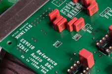
1) Header "CN2" is for I2S input....correct ?
2) Hearer "CN6" is for SPDIF input ?
3) On those headers, the second row (ground) is for ribbon cable "ground interleaving"...correct ?
4) "Mute" and "Lock" are for LED's which can be routed to a front panel if desired. The "Lock" can be a bi-coloured LED, correct ? (common cathode)
5) What is the 3pin header marked "GND, SDA, SCL" used for ?
6) What is the 2pin "/EN" header used for ?
7) What is the 2pin header marked "X1, GND" used for ? (also has 3 SMD pads....looks like for another LED) ??
8) The "Reset" header....would be for a momentary push-button (if ever needed) ??
9) Can someone suggest a descent SPDIF (toslink + phono plug) ??
10) Can someone suggest a descent USB/I2S converter ?
~~~
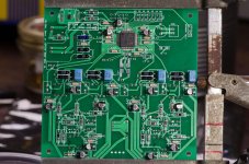
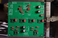
I've stuffed most of the board (see pic).
Not "stock" (tweak) are the 10n WIMA caps paralleled with the 100n SMD bypass caps (opposite sides of the board, around the chip) see pic.
(btw....this is my first time soldering SMD parts)
This is my first venture into digital. I am just a hobbyist.
This is my first DAC project. I realize most of you have built several.
Remember your first DAC venture ?
So I'm asking for a bit of help.
I'm asking my questions in simple form, so that others in my position can also benefit.
My goal is to keep this board/project as "stock" as possible...AD797's throughout, onboard Crystek/950 100mhz clock.
My questions are ultra-basic....mostly routing and hookup.
I'll ask my questions in numbered form, so you can answer them easily.
(mostly yes/no answers)
1) Header "CN2" is for I2S input....correct ?
2) Hearer "CN6" is for SPDIF input ?
3) On those headers, the second row (ground) is for ribbon cable "ground interleaving"...correct ?
4) "Mute" and "Lock" are for LED's which can be routed to a front panel if desired. The "Lock" can be a bi-coloured LED, correct ? (common cathode)
5) What is the 3pin header marked "GND, SDA, SCL" used for ?
6) What is the 2pin "/EN" header used for ?
7) What is the 2pin header marked "X1, GND" used for ? (also has 3 SMD pads....looks like for another LED) ??
8) The "Reset" header....would be for a momentary push-button (if ever needed) ??
9) Can someone suggest a descent SPDIF (toslink + phono plug) ??
10) Can someone suggest a descent USB/I2S converter ?
~~~
I've stuffed most of the board (see pic).
Not "stock" (tweak) are the 10n WIMA caps paralleled with the 100n SMD bypass caps (opposite sides of the board, around the chip) see pic.
(btw....this is my first time soldering SMD parts)
Attachments

1) Header "CN2" is for I2S input....correct ?
Yes
2) Hearer "CN6" is for SPDIF input ?
Some of the pins can be used for SPDIF but it will require that you use the DAC in s/w mode (use Hifiduino for example)
3) On those headers, the second row (ground) is for ribbon cable "ground interleaving"...correct ?
Yes
4) "Mute" and "Lock" are for LED's which can be routed to a front panel if desired. The "Lock" can be a bi-coloured LED, correct ? (common cathode)
Sometimes, both lock and mute can be on.
5) What is the 3pin header marked "GND, SDA, SCL" used for ?
This is for an external controller
6) What is the 2pin "/EN" header used for ?
To enable or disable the clock (for clocks that have enable pin)
7) What is the 2pin header marked "X1, GND" used for ? (also has 3 SMD pads....looks like for another LED) ??
To connect an external clock if you are not using the local clock. Or you could disable the local clock and feed an external clock.
8) The "Reset" header....would be for a momentary push-button (if ever needed) ??
Yes
9) Can someone suggest a descent SPDIF (toslink + phono plug) ??
As it is (without external controller) you can only use I2S or SPDIF but not both. You will connect SPDIF to DATA1 line
What do you mean toslink to phono plug?
10) Can someone suggest a descent USB/I2S converter ?
Both Amanero and diyinhk latest XMOS receivers are excellent choices
Yes
2) Hearer "CN6" is for SPDIF input ?
Some of the pins can be used for SPDIF but it will require that you use the DAC in s/w mode (use Hifiduino for example)
3) On those headers, the second row (ground) is for ribbon cable "ground interleaving"...correct ?
Yes
4) "Mute" and "Lock" are for LED's which can be routed to a front panel if desired. The "Lock" can be a bi-coloured LED, correct ? (common cathode)
Sometimes, both lock and mute can be on.
5) What is the 3pin header marked "GND, SDA, SCL" used for ?
This is for an external controller
6) What is the 2pin "/EN" header used for ?
To enable or disable the clock (for clocks that have enable pin)
7) What is the 2pin header marked "X1, GND" used for ? (also has 3 SMD pads....looks like for another LED) ??
To connect an external clock if you are not using the local clock. Or you could disable the local clock and feed an external clock.
8) The "Reset" header....would be for a momentary push-button (if ever needed) ??
Yes
9) Can someone suggest a descent SPDIF (toslink + phono plug) ??
As it is (without external controller) you can only use I2S or SPDIF but not both. You will connect SPDIF to DATA1 line
What do you mean toslink to phono plug?
10) Can someone suggest a descent USB/I2S converter ?
Both Amanero and diyinhk latest XMOS receivers are excellent choices
Thank you GLT.
I meant ....toslink "and" digital RCA jack inputs (or BNC). One that incorporates both options.
....I'll check your site about a controller.......
What is the degree of difficulty when adding an external controller "?
"What do you mean toslink to phono plug?"
I meant ....toslink "and" digital RCA jack inputs (or BNC). One that incorporates both options.
....I'll check your site about a controller.......
What is the degree of difficulty when adding an external controller "?
Last edited:
Consumer spdif (~1v) needs to be boosted to 3.3v with something like this: The Buffalo III Digital-to-Analog Converter (Single S/PDIF (or AES-EBU) Level Converter Kit)
For toslink you just need a toslink receiver module like this: TOSLINK Optical Input Module
or one of this and take it apart: http://www.ebay.com/itm/Digital-Opt...505&pid=100005&prg=1088&rk=3&sd=121075308720&
To implemented a controller, just follow the instructions and buy the parts")
For toslink you just need a toslink receiver module like this: TOSLINK Optical Input Module
or one of this and take it apart: http://www.ebay.com/itm/Digital-Opt...505&pid=100005&prg=1088&rk=3&sd=121075308720&
To implemented a controller, just follow the instructions and buy the parts
Last edited:
I'm still a bit fuzzy on this....GLT said:As it is (without external controller) you can only use I2S or SPDIF but not both. You will connect SPDIF to DATA1 line.
Is this just how the diyinhk ES9018 board is configured ?....one "or" the other, so that if both are connected...it causes a conflict ?
I see TP has this board....
S/PDIF 4:1 MUX/Receiver Module (using an input selector switch)
...but I see this in the MUX installation guide:
You can use a switch or a
microcontroller to set the register. The inputs can be switched at any time. The selected input will be output at
both the I2S and SPDIF outputs.
From what I can see, AMB is using such a setup (with the switch)....but that's into a Buffalo.
If there is a conflict, could a hardware solution be implemented for switching between I2S and SPDIF ?
...switch or relay(s) ?
...or are we back to "To implemented a controller, just follow the instructions and buy the parts
" ??....lol
Last edited:
I see, the chip has auto-detection, always reverting to SPDIF if data there is present.
http://hifiduino.wordpress.com/sabre32 -LEVERAGING INTERNAL SOURCE SELECTION
http://hifiduino.wordpress.com/sabre32 -LEVERAGING INTERNAL SOURCE SELECTION
I imagine routing and switching the incoming signal through a hardware relay is not optimal...just guessing.Of course if you are using a 4 pole switch where you can completely switch out the I2S signal, then keep the internal switch in automatic and yo get the same functionality.
yes, glt is right (and getting lazy so didnt answer hehe) without a controller the dac starts up in defaults on everything and is stuck on the defaults for everything. the defaults look for spdif on spdif input 1 and input 1 only in default and that same line/pin is needed for i2s.
basically to do what you want to do without a controller will require a hardware hack and it will not be optimal, very unlikely to be cheaper or easier either.
the error caused by a relay or switch for spdif, depends on the relay and layout, you would be better off using one of the ti or potato semi MUX/buffers or an RF relay than a standard signal relay, but then you have termination stuff to take care of; not for beginners, many manufacturers dont get it right. the autodetect is good, but not perfect
....I'll check your site about a controller.......
What is the degree of difficulty when adding an external controller "?
Glt's hifiduino is the best option. It's very easy to implement and you also get display, volume control, filter control etc. Great stuff!
Glt's hifiduino is the best option. It's very easy to implement and you also get display, volume control, filter control etc. Great stuff!
I think I'll do just that !!
Got the Arduino Uno R3, a proto shield kit, and a 16x4 display.
Waiting for the Amanero USB board and some other module parts and molex connectors, etc...
I won't ask all the questions I have still.....most all the info is out there.
Except one....because of my inexperience in writing code....
Is Hifiduino code for the Sabre32 (es9018)....the same for this board, as it is for the Buffalo and others ?
.....Are there any changes to be made after uploading the code, before sending it on to the UNO ? (specifically, the spdif/I2S source switching) ??
BTW.....it would be very helpful if someone would post a "block diagram" for a completed setup. I'll mock one up when I think I'm close to connecting all the parts together.......and post it here, for approval.
Last edited:
connect I2S right
hello
i am building also the sabre 9018 from diyinhk.
i have befor the dac, a dsp with I2S connection,but there are a lot of connection,with other desciption,
so my question is can somebody help me to tell me the right connect,from my digelaty dsp I2S to the diyinhk dac I2S ,it can only
four connections be right.
i am beginner in dac and i think this is not the lightest dac .
i took a link on this post and so you will see.
 https://docs.google.com/viewer?atti...81cba8d36e2f94750136&a=bi&pagenumber=3&w=2000
the I2S is J5
i hope someone can help me
regards mennezoe
hello
i am building also the sabre 9018 from diyinhk.
i have befor the dac, a dsp with I2S connection,but there are a lot of connection,with other desciption,
so my question is can somebody help me to tell me the right connect,from my digelaty dsp I2S to the diyinhk dac I2S ,it can only
four connections be right.
i am beginner in dac and i think this is not the lightest dac .
i took a link on this post and so you will see.
the I2S is J5
i hope someone can help me
regards mennezoe
connect I2s right
ok glt
i am to stupid to copy the shematic,i can also write it.
cs dac -pic1
v+ -12v.
mos pic2
gnd gnd
spiclk pic3
mclk
dsp1
fs
dsp2
sclk
dsp3
data
dsp4
dsps
this isthe I2S connection of my dsp.
also another question.i read there are opportunities to connect,raw differential output, so may be some one can tell me wich points are the rights for left an right and gnd left and right.
so hope someone can help me
- Status
- Not open for further replies.
- Home
- Source & Line
- Digital Line Level
- Build thread for Diyinhk ES9018 DAC on Ebay