well I might be able to more readily if people didnt continuously quote me, asking questions or making incorrect assertions, then cry when its not what they want to hear.
abrax isnt included in that, he just does what he does and forced me to check detail, all good, frustrating but all good. he had something to add. cant say i'll ever need that exact snippet again, but hey.
did you really just ask that again? it has something to do with their being solid state devices scattered all over that ground plane and the circuit functioning due to current/holes flowing between them. it is the new view on electron flow, which has EVERYTHING to do with this subject, 'ground' signal flow, all semiconductors etc.
specifically it means that the charged electrons are flowing FROM the broken ground plane to the dac, not the other way around.
read the ******* link!
but OK I get it, you just want to twiddle mindlessly
ive fixed the situation, you 2 specifically will not hear from me again
abrax isnt included in that, he just does what he does and forced me to check detail, all good, frustrating but all good. he had something to add. cant say i'll ever need that exact snippet again, but hey.
We were talking about issues in the ground plane which is a conductor (you know copper) and suddenly we jumped into n and p channels, semiconductor doping, electron, holes... What's the relation to the ground plane?
did you really just ask that again? it has something to do with their being solid state devices scattered all over that ground plane and the circuit functioning due to current/holes flowing between them. it is the new view on electron flow, which has EVERYTHING to do with this subject, 'ground' signal flow, all semiconductors etc.
specifically it means that the charged electrons are flowing FROM the broken ground plane to the dac, not the other way around.
read the ******* link!
but OK I get it, you just want to twiddle mindlessly
ive fixed the situation, you 2 specifically will not hear from me again
Last edited:
...it has something to do with their being solid state devices scattered all over that ground plane and the circuit functioning due to current/holes flowing between them. it is the new view on electron flow, which has EVERYTHING to do with this subject, 'ground' signal flow, all semiconductors etc.
read the ******* link!
but OK I get it, you just want to twiddle mindlessly
So what? what is the implication to the ground plane? can you be a little more specific?
you didnt at any point explain a more correct view....par for the course...
Certainly par for the course that you'd misrepresent me
 I contributed the correction that its donors (donor atoms) that are being used to dope the semiconductor.
but OK it seems carrier is just another name for hole aka charge carrier. if you actually read the whole post instead of picking a little bit to disagree with, you would see I had the correct gist of it, then linked to more knowledgable folks.
Again a misrepresentation (that I didn't read the whole post) - I agree with glt here, what does any of this stuff about conduction in semiconductors have to do with groundplanes?
an extra electron, or one less electron charge has to come from somewhere, how do you propose they get the excess or lack of them into the implanted atoms? picking a hole in making a positively doped or negatively doped atom and implanting that, with adding or removing electrons is just argument for the sake of it
Its a good question which you can use as a springboard to learn something, I'm outa here
can you ignore a thread?
Sure, just watch me
Certainly par for the course that you'd misrepresent me
actually you are correct, I did misread you, but you were IMO picking on a pretty petty detail about a process I mentioned specificaly I didnt know very much about, since it was mentioned as novelty
Again a misrepresentation (that I didn't read the whole post) - I agree with glt here, what does any of this stuff about conduction in semiconductors have to do with groundplanes?
the fact that all this travels across the board, thats all, in the post I already mentioned it luckily didnt really effect how things work, just the way we visualised the flow between them before was flawed. of course this will probably all change in a few years anyway. It was just by way of explaining that current flow isnt as neat as we would like, so just putting a wire under a resistor is not going to guarantee that the charge behaves itself and goes the way we would like it to go.
nope, its really notIts a good question which you can use as a springboard to learn something, I'm outa here
Sure, just watch me
i'd rather not, but you are the only one left here now, so I guess it'll be deserted.
bye
I just got the Amanero and do a quick test with the 99es9018
There is no listenable unlock issue at 192khz/BCK 12.288Mhz in power on default asyn operation mode for about one hour test. The es9018 onboard oscillator used is fox xpresso 100M from digikey.
but the two onboard adp151 regulator in amanero should have more input and output capacitor as told in hifiduino! my ear is pain when listening if no extra input and output capacitor is added. Four 1uf is parallel with an extra 10uf 0805 on top as in the image
An externally hosted image should be here but it was not working when we last tested it.
Last edited:
perhaps (havent tested this) the default DPLL is 'best' meaning it will try settings until it has stable lock, rather than the very different forced 'lowest'.
that would be best for the users if its 'best'
I havent booted into default for ages and cant remember. both 'best' and 'lowest' appear to be indicated as defaults. it would be good if its 'best' for those not using any kind of controller, as it has much more relaxed requirements for the source jitter, but jitter rejection is not as good. glt probably knows this better than I as thats very much his thing. I know 'best' is default on Buffalo and from memory ackodac, but not sure if its the actual default with no controller at all.
Hoping to build an arduino at some point but at this point, with the exception of the ground plane mod, I've built this as cheaply as possible. Plenty of time to try upgrades, settings etc. One problem I had was the Fox Xpresso 100Mhz osc - a pad came off with a leg. It seems they are far more fragile than the very similar Euroquartz XO91 parts. Anyway, here's a photo. Yes the table needs waxing. The amp is a Mini3, and I re-cabled the HD650 with Double Helix's UPOCC cryo wire. The DAC sounds very good even with the nasty thick film resistors, tl1963 reg, etc. If Diyinhk can make this easier to build then I think he'll sell a truck load of these DACs.
One extra point - I used a bi-colour LED, red-white common cathode, it's red with no signal, white (or flashing white... that's cool) and goes pink when I pause. I used 470r resistors for this and it is plenty bright enough.
An externally hosted image should be here but it was not working when we last tested it.
One extra point - I used a bi-colour LED, red-white common cathode, it's red with no signal, white (or flashing white... that's cool) and goes pink when I pause. I used 470r resistors for this and it is plenty bright enough.
A few extra notes.
I matched two 10K resistors - they both were 10.00K according to my Fluke - for the potential divider that feeds the op amps. With 4x LME49710HA in I/V, and the same (but MA on adapters) in the buffer, I get 1.2mV DC offset on the right and 0.2mV on the left. Awesome.
I mounted most of the larger caps on the top, as you see in the picture, because the op amps in sockets will be a similar height. I mounted the 100pF Wimas on the bottom. They can go on the top but I might want to bypass them if I try a current-feedback op amp in the I/V, and they are also the same height as the oscillator, so they don't add to the height of the board from the bottom or the top. Besides, everything on the top is blue or green or silver or black and that's more than enough colours, and the Wimas are red.
There are no markings for the cap polarity - remember that for single op amps, pin4 is negative voltage and pin7 is positive, so it pays to triple check cap polarity before switching on, as well as checking for shorts across power lines etc.
The Kubota reg that I bought on Ebay and modified for lower noise, has 19.5V across each smoothing cap form the 14-0-14 transformer. So the highest output I can get that's still within regulation is +/-13.5V.
The heatsinks on the Sigma11 have only risen slightly over ambient temp, but this is with a low freq clock. I need to test this with a 125Mhz clock and observe voltages, temperatures, etc, which Mr Fluke can do.
It's hard to give any impressions about sound quality with a Mini3 driving HD650 but I can certainly say this is not a crap DAC, like so much stuff on Ebay and Taobao is.
Have a great weekend all, I know I will...
perhaps (havent tested this) the default DPLL is 'best' meaning it will try settings until it has stable lock,
Would you tell me how you got this explanation? I have never found any documented tecnical explanation on the "default best".
I always appreciate a technical details of "DPLL".
By the way, have you received my private e-mail sent early this year?
i've forgotten where I saw it outlined, think it was Russ. its very vague in the datasheet, but reg 25 mentions 'use the best DPLL settings', as opposed to 'allow all settings' which says to me its something other than 'lowest' or it would just be duplication and it does provide more stable operation.
the post I saw mentioned that it would widen the bandwidth until it had stable lock, thus it uses the 'best' it can given the particular jitter environment. now how dynamic a process that is I dont know, it may just select a setting relaxed enough that it can assure solid lock, or it may actively loosen it until it gets to that point and stop.
thats why I though glt might be more in the know here because hes the sabre google master and may have found something more definitive, or perhaps included it as a factor in his DPLL testing
no I havent seen an email, sorry i'll check in a moment, I probably received it but my mailbox has been pretty flooded lately with group buy stuff. i'll be out all day tomorrow and have got more GB stuff to take care of now to make sure I can get the NTD1 parts out the door on monday-tuesday given I wont be around tomorrow to deal with it, but i'll have a look, or you could resend and i'll get back to you Sunday when I get home.
Hey KlipschKid, congrats!
Will be awaiting your report on the sound and selection of opamps. Have been using my DACs straight Vout so have no experience with the opamps.
Congrats too to diyinhk for providing this board at cost/near cost to us diyers
And of course, congrats to ESS for producing a good DAC chip.
You mean the gnd mod was not cheap?
Will be awaiting your report on the sound and selection of opamps. Have been using my DACs straight Vout so have no experience with the opamps.
Congrats too to diyinhk for providing this board at cost/near cost to us diyers
And of course, congrats to ESS for producing a good DAC chip.
Hoping to build an arduino at some point but at this point, with the exception of the ground plane mod, I've built this as cheaply as possible....
You mean the gnd mod was not cheap?
Last edited:
Haha.. you're right - the copper is cheap... perhaps I should have said I built it badly .... "If it doesn't fit, you're not hitting it hard enough".
I couldn't resist a listen this morning - it's been on all night ....
Bear in mind I have a low-clock freq, a low quality op amp regulator, and noise from the usb getting into it... and you might not be surprised to hear it needs improving. In this configuration, it's not as good as my best DAC, and actually has some technical problems too. It's very detailed, has good depth and space, and is punchy but I don't like the signature - too much "white water" at the top end instead of flowing smoothness, if you can get that meaning = over-bright and some exaggerated detail with a little distortion.... in other words. Not a lot of thd but it shouldn't be there. I'm blaming the usb for this - but wait and see.
Issues to address
- very rare but once or twice it has "unlocked" - it seems a faster clock will solve this
- sound quality varies - there's sometimes an HF crackle, almost vinyl like - which spoils the otherwise dark background
- modify the psu for the op amps. There's something wrong with that Ebay kit. ( No surprises there eh ? Ebay junk... )
- isolate the USB / I2S and power the usb card from the sigma11
I'll very interested to know what you think when you get yours running, because you have the Buffalo to compare it with. For me, I much prefer the sound from the dual AD1955 at this stage. However, I can tell this DAC has great potential because the "low-jitter" is evident.
Anyway, I wanted to find out how bad it could sound and now I know, so next week I'll start upgrading.
cheers
Last edited:
Haha.. you're right - the copper is cheap... perhaps I should have said I built it badly .... "If it doesn't fit, you're not hitting it hard enough".
I couldn't resist a listen this morning - it's been on all night ....
Bear in mind I have a low-clock freq, a low quality op amp regulator, and noise from the usb getting into it... and you might not be surprised to hear it needs improving. In this configuration, it's not as good as my best DAC, and actually has some technical problems too. It's very detailed, has good depth and space, and is punchy but I don't like the signature - too much "white water" at the top end instead of flowing smoothness, if you can get that meaning = over-bright and some exaggerated detail with a little distortion.... in other words. Not a lot of thd but it shouldn't be there. I'm blaming the usb for this - but wait and see.
Issues to address
- very rare but once or twice it has "unlocked" - it seems a faster clock will solve this
- sound quality varies - there's sometimes an HF crackle, almost vinyl like - which spoils the otherwise dark background
- modify the psu for the op amps. There's something wrong with that Ebay kit. ( No surprises there eh ? Ebay junk... )
- isolate the USB / I2S and power the usb card from the sigma11
I'll very interested to know what you think when you get yours running, because you have the Buffalo to compare it with. For me, I much prefer the sound from the dual AD1955 at this stage. However, I can tell this DAC has great potential because the "low-jitter" is evident.
Anyway, I wanted to find out how bad it could sound and now I know, so next week I'll start upgrading.
cheers
-cm6631A must use synchronous clock to avoid the lock issue, the ebay item description has the detail connect instruction. For asyn clock operation, amanero seems the only working solution now. xmos reference board is also tested and it also has lock issue in asyn clock operation.
-same as above
-no problem with the ps to the opamps, the ground is also connected on the bottom layer! it is not only connected on the top layer at one point. Actually, The digital ground and analog ground is segmented in this arrangement to avoid too much noise inject to the analog section.
I am also testing other ground plane arrangement but the current version is work flawlessly
Hi,
I think the "whiteness" is quantization noise because of the low freq clock. I tried a much faster clock and the sound seemed much better. I'll try synch from the CM next.
I notice the board has u.fl connector pads for clock input. Can you recommend a part that will fit this ? I'm not familiar with such parts so your help would be great, especially a part code from Element14 here in HK.... ;-)
The problem with the psu for the op amps is not your board. It is the psu kit I bought from a different seller on Ebay. I think it keeps dropping out of regulation, maybe a dry joint somewhere.
For the ground planes, I think you should think about adding vias between the gnd planes near the I/V resistors. I would also suggest you remove the smd pads for the I/V resistors and allow only through hole. This way, the area under these resistors can be changed into a continuous ground. It's a simple change so people won't need to do the ground plane mod.
Thanks,
Tom
Last edited:
Hi,
I think the "whiteness" is quantization noise because of the low freq clock. I tried a much faster clock and the sound seemed much better. I'll try synch from the CM next.
I notice the board has u.fl connector pads for clock input. Can you recommend a part that will fit this ? I'm not familiar with such parts so your help would be great.
Thanks,
Tom
asyn 100M clock with CM and XM is tested
it will have lock issue.lower than 40M clock is also tested
it will have serious sound distortion problem, I don't know if it's call quantization noise.u.fl is used to connect to an external clock source, wikipedia has many useful information. I heart somebody even use ufl to connect to an atomic clock, but I can't recommed as it's very danger, radiation is hazardous to health and to the surrounding people
Hirose U.FL - Wikipedia, the free encyclopedia
http://www.hirose.co.jp/cataloge_hp/e32119372.pdf
Actually, I think something can at less pleasure myself to pleasure others, I always use smt component
There is always new version pcb coming, 4 layer board should solve the ground plane problem easily, but you may also interest to see our new AK4399 pcb available in this few day, it's 2 layer but it has a newer power trace arrangement in the IV section. the top layer is a complete solid ground plane
Last edited:
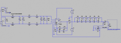
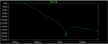
Passive filter output stage for ESS
Here's my first stab (just design and simmed in LTSpice, nothing built so far) for a passive filter output stage for this DAC. Not proprietary, anyone is free to use, copy, modify whatever
Key features - 4th order Butterworth response, HF linear opamp (no LTPs!). Caveats - its designed for great sound, the noise performance won't suit some as the LT6552 isn't a quiet chip. It is cheap though
Attachments
I had wondered about 2 x JG jfet filter buffer on balanced output of IV stage for 9018 but haven't got a 9018 DAC to test it on. Thoughts? Component matching for balanced will add cost but is a pretty simple circuit.
Just a thought, I might have missed something that disqualifies that circuit for the 9018 DAC. I'll be building one for se output of my ES9023
Just a thought, I might have missed something that disqualifies that circuit for the 9018 DAC. I'll be building one for se output of my ES9023
Its not a disqualifier, but the JG filter uses a much bigger inductor (18mH) which resonates around 500kHz due to the parasitic capacitance. Hence rejection at 1.5MHz won't be great. Whereas my circuit seems to have rather a nice notch around that frequency
Attachments
Last edited:
- Status
- Not open for further replies.
- Home
- Source & Line
- Digital Line Level
- Build thread for Diyinhk ES9018 DAC on Ebay