Well, I already forgot about the CFP, it sounds great in it's current implementation.Terry Demol said:
In our experience, CFP is sterile, non-CFP
sings.
WRT BC557/547 Vs 2sa970/sc2240 (BL) , you can get VG
results with 557C/547C but having checked the data sheets
of 970/2240 they DO look even better WRT Hfe linearity vs
current over a wide range, also have very low noise.
Terry
My first SE version was using BC547B initially. Later changed them for the SC's and there was some improvement.
Yep, the linear hfe range is important, datasheet show typical curves. That's exactly why I started using these bjt's.
Terry, any experiences with using darlington's as common base transistors (with some 1k between BE of 2nd bjt) ?
Well, not really, I was just kiddingPeter Daniel said:
Does that mean you are still oversampled?")
How far are you with stuffing the board ?
with all the concern about sufficient gain and compound transistor pairs I think the Baxendall “Super Pair” might be worth exploring in this common-base type circuit, I point to several posts of mine about it in:
http://www.diyaudio.com/forums/showthread.php?s=&postid=220909&highlight=#post220909
And scrolling down to post #236 shows the VAS stage application, but is should be easy to see how to use the super pair (I think I’ve seen it called a “complementary darlington” too) in a common base or cascode type application
6 months ago I made similar circuit (based on Rudolf's schematic here ). I'm using it with my nonos TDA1541 dac. Transistors are BC550C/560C and I didn't install dc servo, so it has coupling caps on the outputs. It sounds much better than single ended version I had before (cleaner, smoother and punchier).
So, Rudolf's new I/V would probably work with BC's too.
So, Rudolf's new I/V would probably work with BC's too.
vuki said:6 months ago I made similar circuit (based on Rudolf's schematic here ). I'm using it with my nonos TDA1541 dac. Transistors are BC550C/560C and I didn't install dc servo, so it has coupling caps on the outputs. It sounds much better than single ended version I had before (cleaner, smoother and punchier).
So, Rudolf's new I/V would probably work with BC's too.
Do you use ana nalog filter?
jcx said:with all the concern about sufficient gain and compound transistor pairs I think the Baxendall “Super Pair” might be worth exploring in this common-base type circuit, I point to several posts of mine about it in:
http://www.diyaudio.com/forums/showthread.php?s=&postid=220909&highlight=#post220909
And scrolling down to post #236 shows the VAS stage application, but is should be easy to see how to use the super pair (I think I’ve seen it called a “complementary darlington” too) in a common base or cascode type application
Hi jcx,
Beautiful little circuit and a great way to get around miller c
modulation (with V) induced distortions.
I actually thougt it up some time ago trying to find a way
to lower distortions I was measuring on open loop
stuff workig into med to high Z's (around 10~20k)
The two mechanisms I isolated were modulating miller
C with swinging voltage and non linear Hfe causing an
"error" current out the base. This pair lowers both by
near the Hfe of 2nd tranny.
I figured this arrangement was used somewhere, and then
just recently saw your posts... good stuff.
As you ave stated, not used much, maybe people don't fully
understand it's true virtues!
This is the great thig about discrete design, we have all these
elements at our disposal to use exactly where/how we want.
Cheers,
Terry
What I see is the one half (single end) of the traditional diamond transistor.jcx said:with all the concern about sufficient gain and compound transistor pairs I think the Baxendall “Super Pair” might be worth exploring in this common-base type circuit, I point to several posts of mine about it in:
http://www.diyaudio.com/forums/showthread.php?s=&postid=220909&highlight=#post220909
And scrolling down to post #236 shows the VAS stage application, but is should be easy to see how to use the super pair (I think I’ve seen it called a “complementary darlington” too) in a common base or cascode type application
Pedja
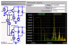
jcx said:super pair common base "cascode" I/V
2 & 20 KHz 1:1 2mA each
baxendall super pair harmonic & IMD > 40 dB down vs single Q
OK jcx stop showing off
These results will be heavily depedant on DAC OP Z.
For PCM63/TDA1541 around 1k, will challenge things
somewhat.
.... but we get the picture as a current coveyor
*with the right conditions* it is very good.
Cheers,
Terry
JCX, Terry,
Is the super pair susceptible to oscillations like the CFP ?
Does one need stopper resistors on the bases, like 22 ohms or so ?
Is there a ratio between the PNP bias current and the NPN current, or is Q1 just set at typically 1mA and Q2 whatever is needed for the application.
I might prepare my next pcb I order to try this:
Attachments
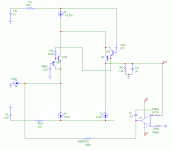
A little bit of history repeating? i.e. Diamonds Are Forever?
Hello JCX,
I must admit that I don’t know what the Baxendall is, but that circuit is definitely nothing more but the one half of the diamond transistor or, more precisely speaking about this application, the diamond buffer. It is known for decades (Hiraga 20W class A was published for the first time in 70s, Mr. De Groove might provide exact date; the Application Note 227 by National Semiconductor is dated October 1979) and is known not only for the good measuring results (though it indeed measures well), but also for its excellent sonics.
The distortion results you are getting in the simulation will differ importantly when, as Terry pointed out, you take in the account an ugly low output impedance of the DAC (that’s the load), so it will be good to put a few kOhm resistor in parallel with the current source that simulates the DAC’s output. In this case, for the total amount of the distortion (if the H and IM distortion that matters), per se distortion of the circuit might play a minor role and some other stuff might be more important.
Attached another option.
Pedja
Attachments
i must admit to playing with the super pair more in simulation than hardware but i have used it in several prototypes without obvious problems
Hawksford does some analysis, but i don't recall comment on stability, some op amp designers have hinted at its instability, but all such comments come before the widespread use of complementary bipolar processes so it may be a consequence of the really poor lateral pnp in '70's IC processes
jcarr gives some bias suggestins in the PSRR thread i pointed to in the earlier reference pointer
certainly the "trick" depends on the current division ratio between Q1 emitter and external source impedance but at 26mV/10mA~=3 Ohm emitter R, a 1K source impedance gives a current division error that is only just approaching the uncanceled Hfe errors of the circuit, in simulation the super pair seems useful in VAS stages with as low as 100-200 Ohm emitter degeneration
Super Pair
About the Super Pair :
I understand the Super Pair behaves more or less like a good old Darlington except that the Vbe of the two transistors compensate instead of adding each other. Can you confirm this, ie. in some cases it'd be simpler to use a darlington rather than a Super Pair...
Any thoughts ?
Re: Super Pair
yes,
You must analyse how the super pair handles
currents due to miller capacitance, and HFE non linearity,
this is the clue to it's HF and overall linearity.
It compensates and reduces these non linear currents
by feeding them back to the emmitter.
Cheers,
Terry
peufeu said:About the Super Pair :
I understand the Super Pair behaves more or less like a good old Darlington except that the Vbe of the two transistors compensate instead of adding each other. Can you confirm this, ie. in some cases it'd be simpler to use a darlington rather than a Super Pair...
Any thoughts ?
yes,
You must analyse how the super pair handles
currents due to miller capacitance, and HFE non linearity,
this is the clue to it's HF and overall linearity.
It compensates and reduces these non linear currents
by feeding them back to the emmitter.
Cheers,
Terry
OK, I now understand how the super pair works ; reducing the linearities by reinjecting the main transistor's base current into the main circuit.
However for me it oscillates ! I've opened a thread for that if you can help me :
http://www.diyaudio.com/forums/showthread.php?s=&threadid=25172
Thanks a lot.
However for me it oscillates ! I've opened a thread for that if you can help me :
http://www.diyaudio.com/forums/showthread.php?s=&threadid=25172
Thanks a lot.
Oscillation??
Hi guys,
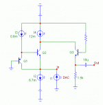
I'm having some problems with this circuit...
When adjusting pot R2 to get 0V DC on the output, the voltage jumps between +12V and -12V and it won't stay anywhere near 0. I am using SA1085 and SC2546. Everything else is per schematic/notes, except the 100r resistors are not surface mount.
Could this be the dark horse of oscillation rearing its ugly head?
Any help/ideas/solutions greatly appreciated
Hi guys,
I'm having some problems with this circuit...
When adjusting pot R2 to get 0V DC on the output, the voltage jumps between +12V and -12V and it won't stay anywhere near 0. I am using SA1085 and SC2546. Everything else is per schematic/notes, except the 100r resistors are not surface mount.
Could this be the dark horse of oscillation rearing its ugly head?
Any help/ideas/solutions greatly appreciated
- Status
- This old topic is closed. If you want to reopen this topic, contact a moderator using the "Report Post" button.
- Home
- Source & Line
- Digital Line Level
- Less simple I/V for TDA1541