My noise and interference issues are gone totally if I lower the volume within the audio application (in this case Squeezelite) massively. For some reason the volume level within the digital signal has been boosted between 8 and 10 times normal, so anything over about 12% volume gets clipping and creates distortion. I'm sure it's a software setting and I need to dig a little further into the ALSA settings, but for now I'm happy that it's working and sounding great with the volumes set low.
Fixed!
")
I needed to change my squeezelite startup string to force 24 bit
so it was
squeezelite -o botic-split -n JRdddac -a 16384:1024::
and now it's
squeezelite -o botic-split -n JRdddac -a 16384:1024:24:
which solved the weird volume issues, but I then had a slight digital white noise/swishing noise in the background. I changed the end of the botic startup string in /boot/uboot/uEnv.txt to read snd_soc_botic.blr_ratio=64 rather than 32 and that has totally cleared up the weird interference noise. It's all smooth and delicious now with beautiful clear and easy detail. Hoorah!
I2S connection
i have my latest version of DDDAC (Tent shunt regulators + pin 20 bias) with the most basic config running (single DAC board).
now I would like to experience the I2S signal input. my player is a Squeezebox Duet. it seems that it is possible to get I2S components as BCK, DATA, LRCK and GND from Duet's board.
is it OK if I connect them to the peer pins on DDDAC mainboard? is it that much simple?
DAC+ pro I2S connection to DDDAC?
Hello All! I've been reading this thread for almost a year now and finally I pulled the trigger and bought myself a DDDAC DIY kit with the motherboard and one DAC board with TENT shunts.
I have a question about the I2S signals used by the DDDAC. I'm planning to feed the I2S signal via Raspberry Pi equipped with the Hifiberry DAC+ pro board, which has its own clocks for I2S. So, do I need to connect the master clock signal to DDDAC motherboard's I2S "mck" connector?
Here's a link to Hifiberry's website explaining the I2S connections of the DAC+ pro board. Should I connect like this?:
DAC+pro________DDDAC
1. ground________ground
2. master clock___no connection or MCK?
3. bit clock_______BCK
4. frame clock_____LRC?
5. data__________DATA
I was also wondering, that will my DAC+pro board be of no use, if the DDDAC has it's own clocks? Maybe I should just connect straight from Raspberrys I2S connections to DDDAC?
Last edited:
Hi James,
This is fantastic! Would you be kindly provide us a more elaborate instructions/directions to achieve this sucesssucessfully, PLEASE!

Many thanks in advance,
Chanh.
This is fantastic! Would you be kindly provide us a more elaborate instructions/directions to achieve this sucesssucessfully, PLEASE!
Many thanks in advance,
Chanh.
Fixed!
I needed to change my squeezelite startup string to force 24 bit
so it was
squeezelite -o botic-split -n JRdddac -a 16384:1024::
and now it's
squeezelite -o botic-split -n JRdddac -a 16384:1024:24:
which solved the weird volume issues, but I then had a slight digital white noise/swishing noise in the background. I changed the end of the botic startup string in /boot/uboot/uEnv.txt to read snd_soc_botic.blr_ratio=64 rather than 32 and that has totally cleared up the weird interference noise. It's all smooth and delicious now with beautiful clear and easy detail. Hoorah!
Hello All! I've been reading this thread for almost a year now and finally I pulled the trigger and bought myself a DDDAC DIY kit with the motherboard and one DAC board with TENT shunts.
I have a question about the I2S signals used by the DDDAC. I'm planning to feed the I2S signal via Raspberry Pi equipped with the Hifiberry DAC+ pro board, which has its own clocks for I2S. So, do I need to connect the master clock signal to DDDAC motherboard's I2S "mck" connector?
Here's a link to Hifiberry's website explaining the I2S connections of the DAC+ pro board. Should I connect like this?:
DAC+pro________DDDAC
1. ground________ground
2. master clock___no connection or MCK?
3. bit clock_______BCK
4. frame clock_____LRC?
5. data__________DATA
I was also wondering, that will my DAC+pro board be of no use, if the DDDAC has it's own clocks? Maybe I should just connect straight from Raspberrys I2S connections to DDDAC?
The above is correct. No need for mck indeed
The dddac has no own clocks for i2s. That is for spdif only...
You can connect any i2s source directly to the mainboard. Not directly to the DAC module. You can all read why on my website by the way.
The above is correct. No need for mck indeed
The dddac has no own clocks for i2s. That is for spdif only...
You can connect any i2s source directly to the mainboard. Not directly to the DAC module. You can all read why on my website by the way.
hello Doede,
and should i assume the same mapping for Squeezebox Duet?
HOW to wire the output of the Sowter transformers ( Doedes special) when connecting is to cinch chassis connector in stead of an XLR connector.
Greetings, eduard
Primary goes to POS and NEG on the mainboard.
Secondary goes to tip and ring of RCA/Cinch connector.
Don't ask me what the "proper" GND connections are, I tend to figure this out by testing different set ups. But I guess the outer ring of the RCA should go to GND of the DDDAC (but sometimes it's better not to do this if you need to break a ground loop or similar).
Sure. I won't get chance for a couple of days, but I'll put a few bits togetherHi James,
This is fantastic! Would you be kindly provide us a more elaborate instructions/directions to achieve this sucesssucessfully, PLEASE!
Many thanks in advance,
Chanh.
Primary goes to POS and NEG on the mainboard.
Secondary goes to tip and ring of RCA/Cinch connector.
Don't ask me what the "proper" GND connections are, I tend to figure this out by testing different set ups. But I guess the outer ring of the RCA should go to GND of the DDDAC (but sometimes it's better not to do this if you need to break a ground loop or similar).
Hello,
I just dont know how to connect the secondairy site of the transformer because it has 3 wires and a cinch connector just have two places to solder something.
So where are the pink, orange and brown wire going.
Thanksalot, Eduard
Hello,
I just dont know how to connect the secondairy site of the transformer because it has 3 wires and a cinch connector just have two places to solder something.
So where are the pink, orange and brown wire going.
Thanksalot, Eduard
Didn't you receive any documentation with your Sowters?
My Sowter seems to have different color code. Here's my secondary set up:
pink: signal
brown: GND
grey: not connected
Primary on my Sowters is red and white.
Didn't you receive any documentation with your Sowters?
My Sowter seems to have different color code. Here's my secondary set up:
pink: signal
brown: GND
grey: not connected
Primary on my Sowters is red and white.
Input is red and white do no use the grey
Output is pink brown. The orange is the center tap. You can use this for balanced loads or to reduce output voltage by half...
By the way, this information is all on my website in the technical document at the download section...
Last edited:
Hello,
There is indeed some info on the website but only a xlr is pictured and i think most people ( like me) will use a cinch connector for output to the pre amp but now we know how to do it thanks!!!
Hoping to be able to play cd within a few days.
Then will focus on a power supply for the wave IO. I wanted to use a choke input but Doede told me to take that the voltage given to the board should be 5 volt +- 100mv so there should be some kind of regulation.
Doede is using an Aurender, thinking about getting one too later.
If i just need to get a power supply for the wave IO and buy the aurender it will be easier then adding a heap of circuits which sometimes still have issues.
What to use for ripping my cd collection when using the aurender? would i be sensaible to get a decent cd rom drive? just got a new one but it is far noisier than my old Philips who broke down after 8 years.
Greetings, Eduard
The choke supply is great for the analog section of the dac, but the digital stuff has different requirements.Then will focus on a power supply for the wave IO. I wanted to use a choke input but Doede told me to take that the voltage given to the board should be 5 volt +- 100mv so there should be some kind of regulation.
The analog section provides the voice for the dac to sing the music, so it benefits from a power supply which is very free and without restriction and which can react quickly to changing demands. The demands on this supply change depending on the music, so you want something dynamic here.
For the digital sections, they generally have quite fixed requirements and as long as they do not have their power drained or interfered by the analog requirement then are happy with a nice quiet regulated supply usually with quite a small current of a few hundred mA or so. Most regulators will not filter noise much above a few hundred kHz it seems, so for digital parts which run in the mhz and ghz then local capacitors are more important. High speed decoupling caps as close to the device as possible work nicely.
That's my take on it anyway. Hope that helps somehow.
James
Hello James,
Your words look very familar to me. Lol. It seemd like you did copy and post an old post of yourself.
Maybe this could be the reason that i wanna try a choke input in a differential mode with a 4000mH Lundahl. I could use this one if i decide to use a serie regulator. If i will use a shunt current drawn will be to high for this one so will have use a choke similar to the one i am using now 700mH 1A
I did read about the Belleson. They look promising but they are expensive but just need one.
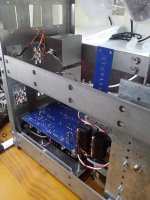
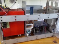
Today i did finish the dddac output wiring. Tomorrow will buy some wood to replace the support of my present dac because the dddac has some extra height. Now weight without front plate is around 32 kilogrammes and it is on the some height as my head so i must take care choosing the parts surrounding the wave io but that will be just a samaller r core and two chokes and some aluminum to support these so probably will end up around 40 kilo.
Maybe i have to do a warming up before lifting it that high.
Greetings, Eduard
Your words look very familar to me. Lol. It seemd like you did copy and post an old post of yourself.
Maybe this could be the reason that i wanna try a choke input in a differential mode with a 4000mH Lundahl. I could use this one if i decide to use a serie regulator. If i will use a shunt current drawn will be to high for this one so will have use a choke similar to the one i am using now 700mH 1A
I did read about the Belleson. They look promising but they are expensive but just need one.
Today i did finish the dddac output wiring. Tomorrow will buy some wood to replace the support of my present dac because the dddac has some extra height. Now weight without front plate is around 32 kilogrammes and it is on the some height as my head so i must take care choosing the parts surrounding the wave io but that will be just a samaller r core and two chokes and some aluminum to support these so probably will end up around 40 kilo.
Maybe i have to do a warming up before lifting it that high.
Greetings, Eduard
Attachments
Analog supply in DDDAC design, does not really exist. The +12V supply is used to supply a digital I2S isolator located on XMOS board and the digital sections of DDAC decks. Hence, all supplies should adhere to fast digital decoupling principles... and avoid the darn chokes altogether.
The validity of this argument is further supported by fact that the latest shunt DDDAC decks already take a very good care of “analog” section of DDDAC decks through shunts implementation. Their very low output impedance will do wonders, especially in mixed signal design.
+5V supply has to be of very high quality, and it has to be able to provide very fast digital decoupling to XMOS board.
This was my theory from the early stages of experimenting with DDDAC. The more I thought about it, and the more I experimented with power supplies and chokes, the more it was obvious that chokes simply could not match a properly decupled voltage regulation, especially for XMOS board. This board draws very large amount of constant current, while at the same time, it has to be able to swing its I2S output at very fast rates.
Still, I am not saying that the sound of chokes (even if used in +5V XMOS supply) is bad, better, or worse compared to anything else. Whatever shakes your boat is fine by me.
I just mentioned what I found by a fair amount of measurements undertaken, and a lot of experimentation
Hello,
Today i wrote a message to Belleson to have some more information about the regulators that they have on offer to substitute the LF50 and the two LF33 on the mainboard.
AND of course the 5 volt 500mA ( maybe this one will be used to close to its limits?)or 2A for the wave IO supply.
I rememember reading some people did replace the 3 regulators on thje mainboard by Tent shunts if i am correct.
The Belleson are serie regulators so easier to install then the shunts. They have low voltage drop so probably just desolder the LF regulators and replace them with the Belleson which share the same pin out as the LF types.
Use google translate for the next link from Norway.
Of course it is about the dddac
DDDAC 1794 NOS DAC
I am sure that there is more info to be found if google translate will be able to translate it.
greetings, Eduard
Belleson Vregs and Load Resistors
I use the 2amp Belleson 5V Vreg located right at the input terminal block of the WaveIO. See picture below. I made up a perfboard. I measured a load of about 450ma. I supply it with 7.5V from a 6.3VAC filament transformer with Schottky diodes and filter caps so the Belleson has to throw away 2.5 Volts of heat. A 12V supply would mean 9.5 volts of heat to dissipate which would require a HUGE heat sink. I thought I heard a SQ improvement from the Belleson here.
I also use Bellesons on my red main board and SPMs for the 3.3V digital sections of the DDDAC board which also sounded better to me. I asked Belleson if this Vreg required a minimum load to give the best regulation and they said YES - minimum of 10ma for the SPM. The PCM1794 uses much less than 10ma digital power so I added a 300ohm load resistor to increase the load which I thought also sounded a hair better. Maybe the standard LM33 Vreg would sound better if it had a 300 ohm load resistor.
I highly recommend Belleson for digital circuits.
Attachments
Hello Carlsor,
I wanted to use the same idea for supplying the 5 volt to the wave IO. I think current drawn also depends on the sample rate so that is why i also wanna use the 2A model.
I think using long cables between the regulator and the circuit could harm the benefits of the regulator.
I did ask Belleson if a choke input power supply would be benificial for this 5 volt supply. On their website they write no preregulation is better but then a bigger cap could also be seen as some kind of regulation .
I will wait for their answer.
Of course the LF50 and LF 33 also have a LCLC supply at the input shared with the 12 volt needed to supply the 10 volt regulator which feeds the shunts.
Does the heatsink for the 5 volt has to be that big after all you are not waisting a lot of voltage across it?
Greetings, Eduard
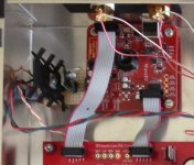
yes, it is best if a signal is applied to the DAC. if nothing is connected the internal clock features of the dac can run hot as it sees nothing to correlate with.
of course you could switch on spdif, than there is always signal if for whatever reason you do not want to connect the WaveIO to the DAC
Hello,
Did use a switch to choose between spdif and wave io but did not connect the wave io board with the flat cable to the motherboard and with the other flatcable to the ledboard.
Did just mount the switch on the chassis. While moving the chassis around on my kitchen table i probably moved the switch over to the other side because when chjecking the input voltage to the mainboard it was 11,9 volt while so far it was always over 12,2 volts.
So moved the switch and it was the higher value again.
Did i do something wrong?
Will it be ok to just attach the wave io with the 2 flat cables.
The two '' switches '' on the wave io will be set as delivered one J12 ( for external 5 volt supply) the otther BRD ( for usb input)
Have no 5 volt supply to connect yet but will be safe to use it this way just in case i might flip the switch again?
Of course once it is in the rack the switch will be rock steady.
I was hoping to put in the rack but i guesss i will have to wait for an answer.
Greetings, Eduard
- Home
- Source & Line
- Digital Line Level
- A NOS 192/24 DAC with the PCM1794 (and WaveIO USB input)