Sorry for delay, steep learning curve with Eagle PCB software.
I have enclosed design notes including LCD schematic, BOM as requested plus Arduino sketch code.
I don't pretend this is the most elegant solution, but it works.
Best Regards
Thanks for that AudioH, very nice indeed. When I come to put mine into a box I might look into a similar solution.
Progress so far, All soldered up including the three power supplies, I did not want the Dac stack sharing with the SPDIF board.
I have drawn up a case and sent the details off to be machined at our local engineering shop, and primed the Powder coaters to expect some alloy panels appearing through the side door for some Black")
There is nothing new done that has not been shown here so I will not bore you with another photo, but I will show how the case comes out.
Then wait for the Transformers to arrive for final wiring, probably another 2 weeks before the big test
I have drawn up a case and sent the details off to be machined at our local engineering shop, and primed the Powder coaters to expect some alloy panels appearing through the side door for some Black
There is nothing new done that has not been shown here so I will not bore you with another photo, but I will show how the case comes out.
Then wait for the Transformers to arrive for final wiring, probably another 2 weeks before the big test
DSD1794 successful
I have tested NOS with DSD1794 (thanks Doede for the great idea, sounds soooo good!), here is the Arduino i2c code to share, PIN3 (DSD clock) needs to be applied after switching from PCM to DSD, I am using the Amanero board to disable DSD clock with the DSD-enable PIN when it's PCM.
PCM,
Wire.beginTransmission(0x4c); //right channel
Wire.write(B00010010); //start with register 18
Wire.write(B00100000); //DF
Wire.write(B00000001);
Wire.write(B00011000); //same as left channel
Wire.write(B00000001);
Wire.endTransmission();
Wire.beginTransmission(0x4f); //left channel
Wire.write(B00010010);
Wire.write(B00100000);
Wire.write(B00000001);
Wire.write(B00011000);
Wire.write(B00000001);
Wire.endTransmission();
DSD,
Wire.beginTransmission(0x4c); //right channel
Wire.write(B00010010);
Wire.write(B00101000); //enable DF bit as well, otherwise cannot switch back to PCM, using DSD filter-3 to get similar gain as PCM
Wire.write(B00000000);
Wire.write(B00101100);
Wire.write(B00000010);
Wire.endTransmission();
Wire.beginTransmission(0x4f); //left channel
Wire.write(B00010010);
Wire.write(B00101000);
Wire.write(B00000000);
Wire.write(B00101000);
Wire.write(B00000010);
Last edited:
Performance improvement continues
Further to my earlier posts, an update on changes that provided improvements in sound quality
Common mode Choke- Added one Panasonic 82mh Common mode choke after the raw supply. This improved the quality of sound, especially with regard to bass resolution. Reasons for this could be rfi noise mentioned before.
I/V Resistor- There was a mention by Bas about Rhopoint resistors earlier in the thread. The quality of this was also mentioned by ECDesigns in his thread on TDA1541. Bit the bullet and ordered these from UK. Since 34 ohms was not available, i paralleled two 70 ohms for each position to reach 35 ohms value. The major improvement I noticed over the Dale resistor was a more natural feel to the sound. The slight metallic edge noticeable with Dale was absent and the dynamics, especially on sharp cymbal strikes was closest to a natural feel.
Since I used .01% resistors, another benefit was that the voltage balance between plus and minus outputs was zero volts as measured with my DMM
There be a difference in the microvolt range, but I do not have the equipment to measure. In contrast,with the dales in position I measured around a difference in the mv range (forgot to note the exact value)
The zero value difference encouraged me to try out transformer coupling yesterday. I used an old Opamp labs 10k:10K transformer for this purpose. I was not expecting much, but once again an improvement. But at first, it comes across as a softening of the sound, As you continue to listen, one notices the more natural feel to voices and greater dynamic swings in the music. Unable to account for this. The only possible explanation is that isolation of the grounds probably has a role.
Anyway, one of my most rewarding and exciting DIY journeys.
Cheers!
Ravi
Having been very lucky and grateful to a fellow DIYAudio member IanS1, who built my DDDAC for me recently, I thought I would share initial listening impressions.
Ian has a very well matched and refined system, with great transparency which is ideal for testing changes. We compared his DDDAC build (4 dac boards and upgraded output caps) to mine (single dac with standard caps). Its clear that the extra boards add a little more refinement, a bit more air, and a sharper focus to the soundstage.
I brought the dac back and put it into my own system and it sounded great - really dynamic. I have made a good number of changes recently in a bid to downsize my set up. So consequently I lack a firm reference to draw upon. Once I've got my ears around what the relative contribution of new active speakers, new preamp, addition of mains reconditioning, and now a newly built dac, all bring - I'll report back!
The new preamp and dac have foxed me to be honest, so with a little swapping out of each I might pin point whats what.
Definitely think the extra dac boards is going to be on the cards - possibly Sowters if they match the input on my preamp.
This is my problem as well. I'm planning to assemble my RAKK DAC MKII (PCM1794 based as well) soon and compare it side by side with the DDDAC PCM1794 NOS. Ofcourse there will be differences because one is spdif the other usb. But I'll compare them to each other without any output caps.So consequently I lack a firm reference to draw upon
Rhopoint resistors
Hi Doede,
The Rhopoint resistor can be purchased online from the company directly. Their web address is :Temperature Sensors, Pressure Transducer, Dynamic Braking, Load Bank, Motor Control
I used the through hole resistor described as 3ppm/°C wirewound econistor 8E16 / 8G16 series.
There are other series which are higher in price for almost similar specification, but I went for the lowest cost option.
Cheers!
Ravi
Rhopoint Squaristor GG102A is the one that beat the Texas Components TX2575 Bulk Z-Foil resistor.
RESISTORS Precision (through hole) 3ppm/°C wirewound squaristor GR102 / GG102 series
RESISTORS Precision (through hole) 3ppm/°C wirewound squaristor GR102 / GG102 series
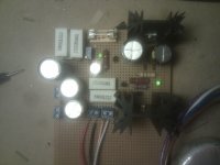
Soldered the 5V PSU
Hey guys,
I just finished the 5V PSU. It is my largest soldering project to date I am very happy to report that it actually worked the first turned it on
It looks a bit less pretty than those with the PCB dd made, but I wanted to make it as DIY as I could, since I'm doing it to learn electronics and soldering.
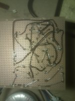
What do you guys think, is this an acceptable way of doing it? You can see in the traces that it turned out rather complex, I honestly drew the diagram on paper first to make sure I wouldn't have wires all over the place, but I made some mistakes I discovered while soldering, so I ended up with some weird bridges anyhow.
Is there anything I can do to test it beyond measuring it with the multimeter?
Next item on the list is the 12V PSU, is there anything you guys would recommend me to do differently?
Hey guys,
I just finished the 5V PSU. It is my largest soldering project to date
I am very happy to report that it actually worked the first turned it on It looks a bit less pretty than those with the PCB dd made, but I wanted to make it as DIY as I could, since I'm doing it to learn electronics and soldering.
What do you guys think, is this an acceptable way of doing it? You can see in the traces that it turned out rather complex, I honestly drew the diagram on paper first to make sure I wouldn't have wires all over the place, but I made some mistakes I discovered while soldering, so I ended up with some weird bridges anyhow.
Is there anything I can do to test it beyond measuring it with the multimeter?
Next item on the list is the 12V PSU, is there anything you guys would recommend me to do differently?
Attachments
...close to opamps decouple your psu with tantalum caps
erm... which opamps ?
Hi Blitz,
A real choke is always better but it's bulky in comparison. You are right, you cannot use it as choke input, than it should be mounted behind the first cap. But I measured current and one board is doing 260mA with shunt regulators mounted so the idea will not work anyway.
The two last boards have arrived this afternoon so tomorrow they will be mounted ( with shunts) and judging of the sowters can start finally!
Than the next step will be to try Salas regulator supplies.
Regards,
Any thoughts on the Sowter transformers?
Hi,
I have tried the sowters and they are good. Better than, I guess, any capacitor.
But..................
As I am using a very nice input/volume transformer in the shape of an audio consulting silver rock in my amps, I have disconnected the ground from the primary of this trannie and connected the dac directly, balanced, without any sowter or capacitor. This is even a step better than the sowter. I could use the extra gain the sowters provide, but not to the expence of sound quality.
And now the icing on the cake is the salas shunt regulator, this is another step in dynamics, openness and detail. Now the complete power supply is shunt regulated (as you know I have already exchanged all regulators on the dac boards for Tent regulators).
This really is the best (but not cheap or easy) upgrade one can make!
I cannot judge the effect of a salas shunt with the original series regulators on the dac boards, there may be an effect but if it is worth the trouble?
I am a big fan of shunt regulating or not regulating at all (LC filters for amps). With series regulators there is always a backdrop in transparancy and dynamics. The big advantage of shunt regulating is that they not only source current but they also sink current! Think about what this means ..................
The other nice thing: The dac now has an extremely short analog signal path, only the I/V resistor (and that is not even in series).
I must say a BIG thank you to Doede for a nice, simple and effective design, I expect the dac in my current version will outperform 99% of all converters on the market.
Kind regards,
Last edited:
Hi Doede,
In the email you mentioned that do not connect the center tap of the output transformer to common. Can you explain a bit on that? I read this artical AN-912, and did some research on the 1794 transformer output, connecting the pos and neg to the transformer, and then connecting the center tap to common, this seems a very popular connecting method, and somebody even mentioned the center tap has to connect to common on other forum, because the DC current saturates the steel core if the center tap does not connect common.
In the email you mentioned that do not connect the center tap of the output transformer to common. Can you explain a bit on that? I read this artical AN-912, and did some research on the 1794 transformer output, connecting the pos and neg to the transformer, and then connecting the center tap to common, this seems a very popular connecting method, and somebody even mentioned the center tap has to connect to common on other forum, because the DC current saturates the steel core if the center tap does not connect common.
First Thanks to super surfer for great review and also for going way beyond typical DIY tweaks. this is not done easily and I can tell you, I do play with the thought of implementing s simple form of shunt regulation on the boards for any future version. but before anyone asks, this will not be soon
on the center tap.....
I get this questions more often, as now several people are using output transformers. Indeed it is confusing to not use a center tap in a balanced output, it seems..... normally when there is no DC bias I would agree. BUT on the DAC output you have the POS and NEG terminal, both at 2,7 Volts DC versus ground.
If you connect these two to the input of transformer WITH a center tap, you short cut the Rload resistor with the DC resistance of the transformer. which in my case is just a few ohms. the results is, that the whole delicately designed bias point for the dac is gone.... not the mention the negative effects of DC running through Signal transformers without having an air gap, but that is even not the most important here.
hope this clarifies...
Doede
Hi Doede,
In the email you mentioned that do not connect the center tap of the output transformer to common. Can you explain a bit on that? I read this artical AN-912, and did some research on the 1794 transformer output, connecting the pos and neg to the transformer, and then connecting the center tap to common, this seems a very popular connecting method, and somebody even mentioned the center tap has to connect to common on other forum, because the DC current saturates the steel core if the center tap does not connect common.
by the way, this article is theoretically correct, but they leave the most important part away, the DC bias of the dac output.... the idea of this document works only, when the dac output is designed to work at zero volt DC output and swing around this point....
- Home
- Source & Line
- Digital Line Level
- A NOS 192/24 DAC with the PCM1794 (and WaveIO USB input)