Disassembling 4 boards
HI All,
I have been using the 4 board version since April last year. I have purchased the tent shunt regulators to be used like Supersurfer has shown in his version
I now need to desolder the connecting wires without damaging the boards and preferably not cutting the silver wires as I would like to use them. Any tips on the best approach based on your experience?
Cheers!
Ravi
that won't work... better cut the wires as low as possible and re-solder them later
you can also do the 8 Volt first, as you can also cut the end of the inductor (so no Need to remove the LDO and than connect the 8 Volt from the side and get the 12 Volt directly from the power supply to the side of the board
you can also do the 8 Volt first, as you can also cut the end of the inductor (so no Need to remove the LDO and than connect the 8 Volt from the side and get the 12 Volt directly from the power supply to the side of the board
Thanks Leif, Sowters are integrated with DDDAC very well! I have heard DDDAC running direct without caps, resister, and transformer to Balance input Preamps. I didn't like it! To my ears the sound were too clean, dry and lack of 3D. With Sowters bring the best out of DDDAC, sound more balance, where I could appreciated for the better.good!
if it´s connected to a TVC, ditch the Sowter and try without if you dare
nothing beats NO cap or NO transformer however good imo
best
Leif
Best,
Chanh
Can anyone advise the minimum wattage rating for the I/V resistors?
I've read very good things about the Rhopoint GG102A resistors
GG102 Series Precision Wire-wound Squaristor (just got a quote and they're roughly £7.50 + vat each for the 0.01% or £5.50 + vat for the 0.1%)
But for the 0.01% 'A' versions, they're only rated for 0.2W
I can't imagine there's much power in this position, but thought I'd double check
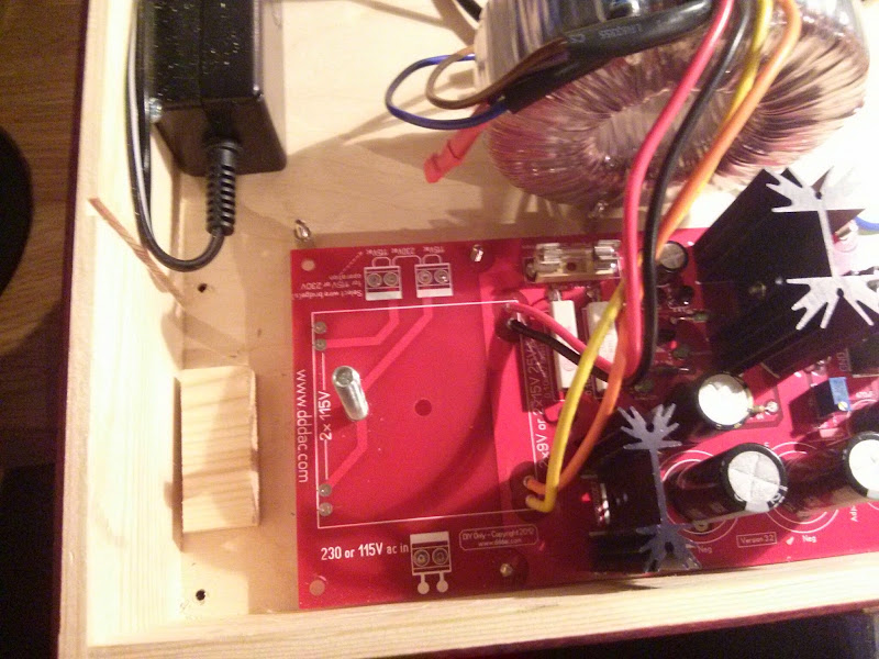
Just thought I'd share a couple of photos here of my DDDAC. Only a 1 x dac board for now and because I knew it would develop and change, I mounted it in a wooden wine bottle case, as it's cheap and easy to cut and change ")
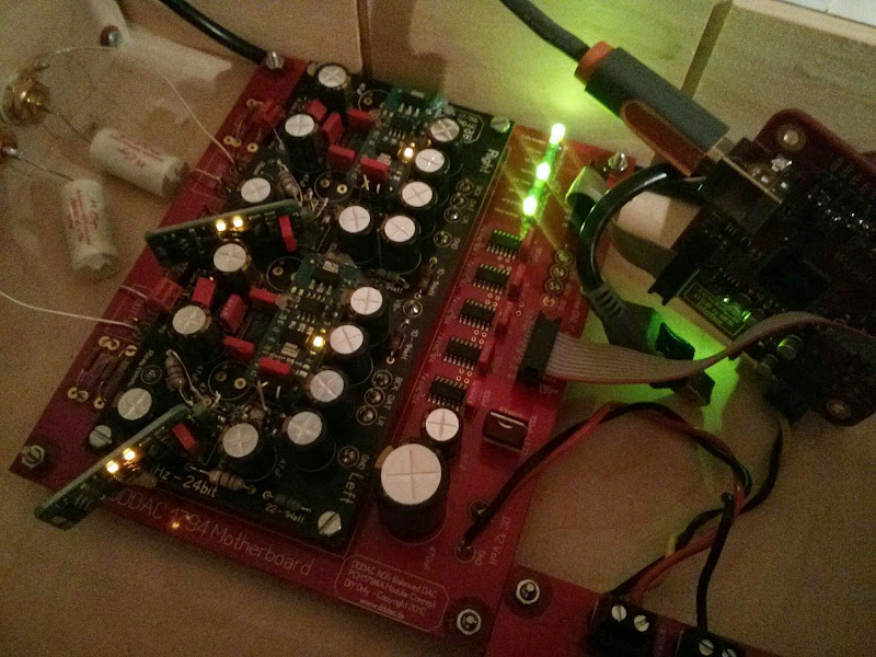
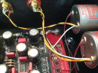
I knew I wanted to fit shunt regs, so when I initially built the dac board up, I placed these 2 Wima caps on the underside, to make room for the shunt above

I also removed the 3 x 47uf Electrolytic caps by the DAC chip where there was also a film decoupling cap. so I could fit the new shunt regs in place like this:
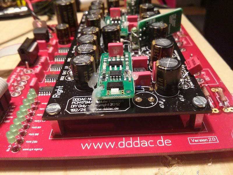
Only a little hot glue needed to hold them totally steady. Legs were extended a little with some pieces of header pins
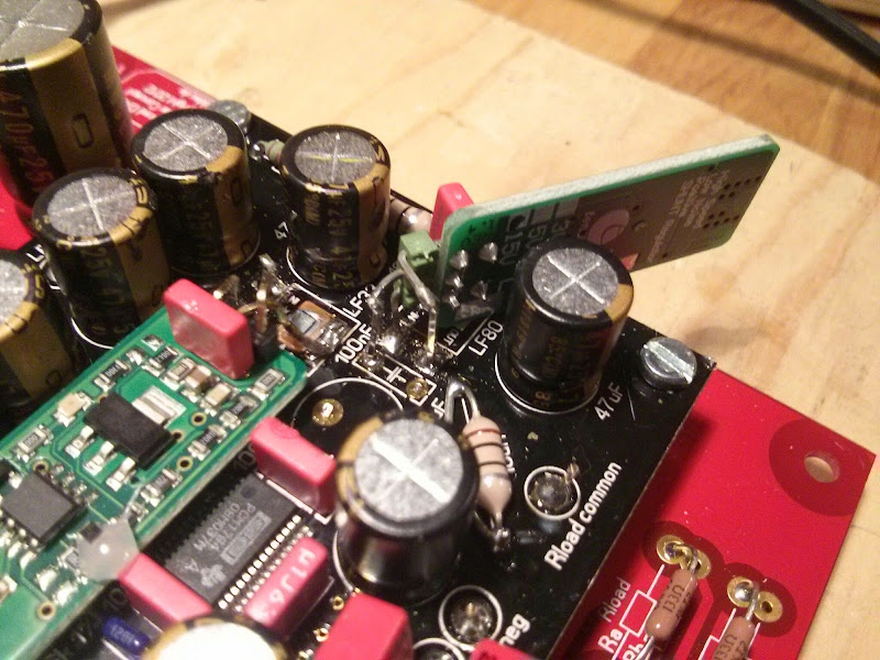
You can see in the middle of this picture that I've bypassed/bridged the L4 chokes with a piece of wire.
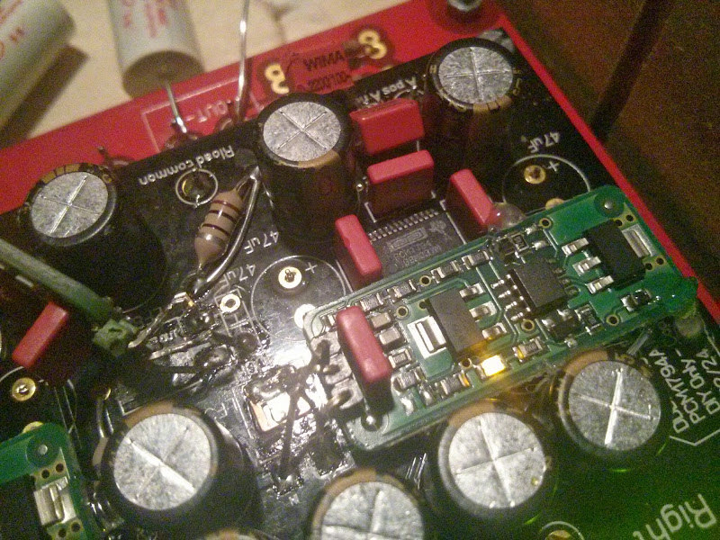
and some small film caps across the a-pos to b-pos and a-neg to b-neg to reduce quantization noise.

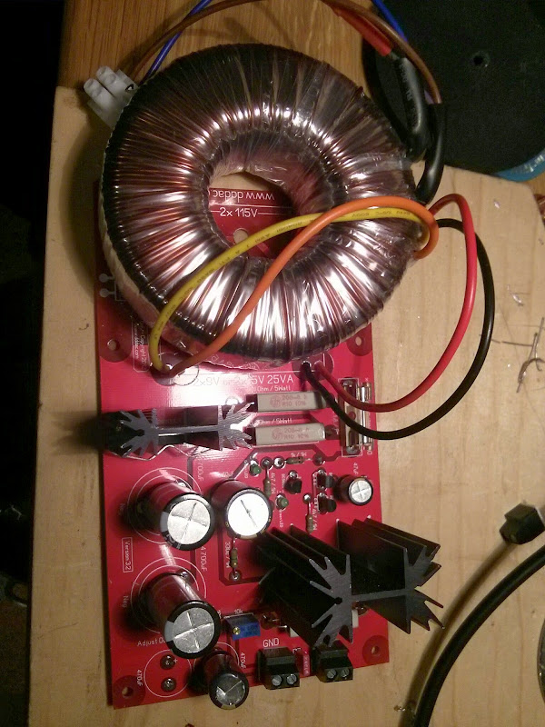
I've also fitted a larger 160va toroidal to my 12v power supply.
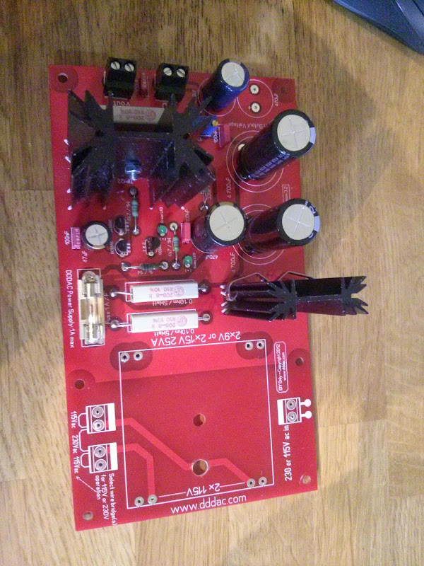
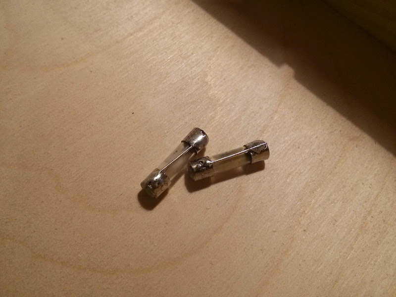
I've bypassed the first 2 5watt resistors with wire bridges, but kept my fuse holders in line.

This way, I have the option of using the standard fuses for after I've changed stuff, to be sure it's safe, or I could buy some expensive low impedance audio fuses, or use my own special Hifi mega low impedance fuses...
Also changed the last 2 x 470uf caps for a 1,000uf 25v Panasonic FC

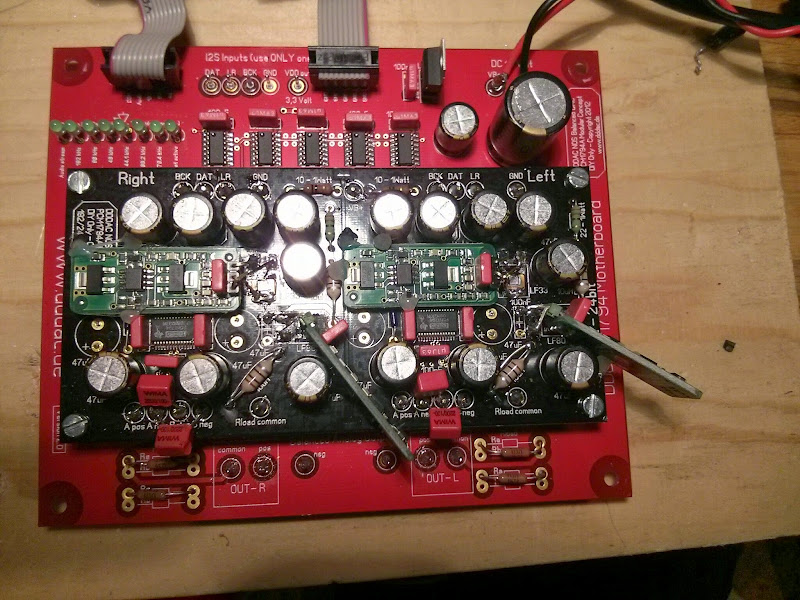
I made the cap change and the fuse shorting modifications to the 12v and 5v supplies.
All back in it's box (Wandboard screwed to the lid)
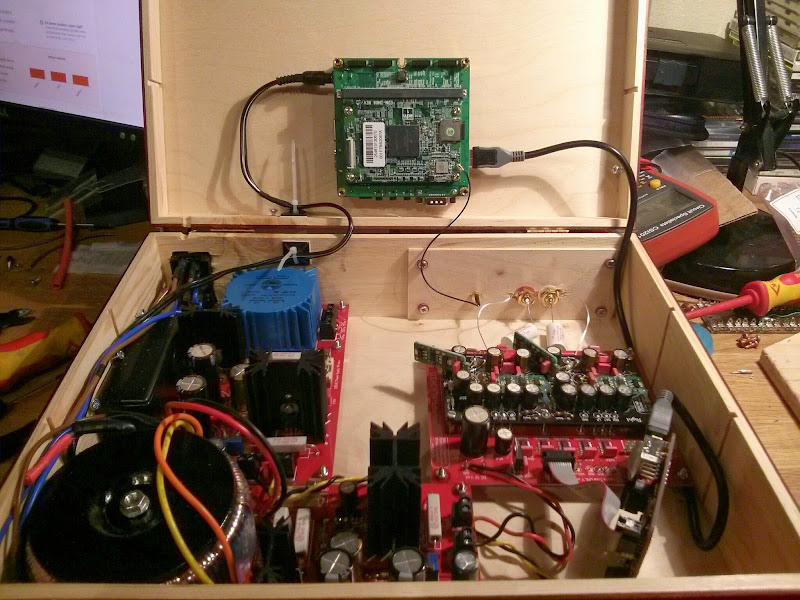
The pleasing glow with it turned on
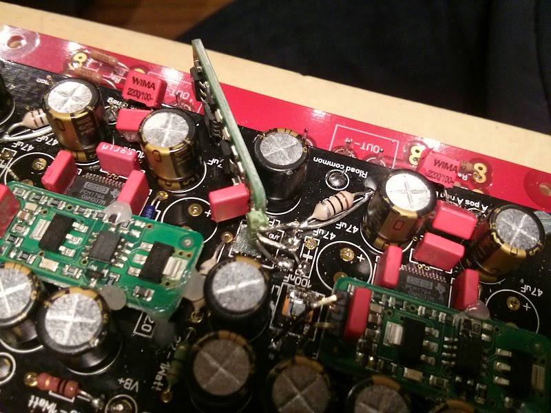
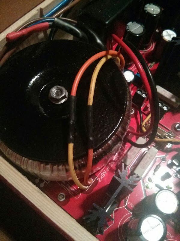
And the little modification I made to the wiring after it all worked, but the new toroidal was making an angry buzzing...
Now it's silent
How does it sound? Very nice indeed I only finished last night and haven't had a full volume blast just yet, so I need to do some more listening, but impressions are goooood
I'm really enjoying listening to my music much more and exploring my collection over again.
Hopefully my Cinemags will be here soon, then maybe it's time for DAC board number 2 and some I/V resistors...
Big thanks to Doede for his amazing kit and also to the guys here for sharing their skills and experiments
cheers,
James
I knew I wanted to fit shunt regs, so when I initially built the dac board up, I placed these 2 Wima caps on the underside, to make room for the shunt above
I also removed the 3 x 47uf Electrolytic caps by the DAC chip where there was also a film decoupling cap. so I could fit the new shunt regs in place like this:
Only a little hot glue needed to hold them totally steady. Legs were extended a little with some pieces of header pins
You can see in the middle of this picture that I've bypassed/bridged the L4 chokes with a piece of wire.
and some small film caps across the a-pos to b-pos and a-neg to b-neg to reduce quantization noise.
I've also fitted a larger 160va toroidal to my 12v power supply.
I've bypassed the first 2 5watt resistors with wire bridges, but kept my fuse holders in line.
This way, I have the option of using the standard fuses for after I've changed stuff, to be sure it's safe, or I could buy some expensive low impedance audio fuses, or use my own special Hifi mega low impedance fuses...
Also changed the last 2 x 470uf caps for a 1,000uf 25v Panasonic FC
I made the cap change and the fuse shorting modifications to the 12v and 5v supplies.
All back in it's box (Wandboard screwed to the lid)
The pleasing glow with it turned on
And the little modification I made to the wiring after it all worked, but the new toroidal was making an angry buzzing...
Now it's silent
How does it sound? Very nice indeed
I only finished last night and haven't had a full volume blast just yet, so I need to do some more listening, but impressions are goooood I'm really enjoying listening to my music much more and exploring my collection over again.
Hopefully my Cinemags will be here soon, then maybe it's time for DAC board number 2 and some I/V resistors...
Big thanks to Doede for his amazing kit and also to the guys here for sharing their skills and experiments
cheers,
James
ss: what values BG N are you looking 4?
best
Leif
Hi Leif,
I am looking for WKZ 47+47uf@500v. I can trade with BG NH 68uf@350v (non polars), NH 100uf@160v and X 2200uf@6,3v and several others, all new.
But I suppose its better to move this to another thread................
James,
Your mods look very nice, good solution the way you put the 3.3v shunts on the board.
Thanks for sharing.
Regards,
Nice build !
Hum, don't you need more boards to achieve the good bas cutoff with cinemags (parallel boards to lower impedence) ?
I understood it was only the custom Sowter transformers which needed a minimum of 4 dac boards?
I borrowed a pair of Cinemags a week or 2 ago and they sounded great in this 1 dac system.
I understood it was only the custom Sowter transformers which needed a minimum of 4 dac boards?
I borrowed a pair of Cinemags a week or 2 ago and they sounded great in this 1 dac system.
Yep, one board and Cinemags sounds OK, I think it's the best upgrade...
Can anyone advise the minimum wattage rating for the I/V resistors?
I've read very good things about the Rhopoint GG102A resistors
GG102 Series Precision Wire-wound Squaristor (just got a quote and they're roughly £7.50 + vat each for the 0.01% or £5.50 + vat for the 0.1%)
But for the 0.01% 'A' versions, they're only rated for 0.2W
I can't imagine there's much power in this position, but thought I'd double check
Ohms law will do also here
DC Output is 2,7 Volt, so power dissipation is 2,7 * 2,7 / Ri/v
or 7,3 / R
example:
1 deck 7,3 / 134 = 55mW
8 deck 7,3 / 17 = 430mW
if you use Ra AND Rb Position, values go by half of course...
rule of thumb, use for power Rating double the disipation
Hi James,
well, you brought DIY to a new Level. Very good idea for experiments with the fuses...
Hope the transformers arrive soon, as I see you still Play with the Standard Mundorf capacitors. I alway find it interesting that with tweaking Audio, there seem not to be Kind of bottlenecks which blocks all the rest... like with relatively simple couple capacitors you still hear an improvement when doing small tweaks
Hi deode just an idea....would it be possible to just stack the pcm1794 dac chips onto each other using an ssop to dip adapter with long pin female headers and using one 3.3v psu for the digital sections and one 8v psu for the analog section.The first dac chip would of course be tied up to all the resistors, caps and what not for signals and all.
If it is possible than I might give it a go as this would lead to less component count and space saving. Not sure if the values of the decoupling caps, resistors and what not needs changing though.
Hope to have some input regarding this from you or anyone else. Thanks.
hi doede,
any feedback/suggestions to the concept's question?
best regards
well who cares? haha just kidding, why would you have a forum name like that?
on your question.....
basically this is what I did with my TDA1543 dac series.... still working well. point is that is difficult to build for the normal DIY. Also I wanted to have every chip a truly own power supply environment .... some times decisions are not black white, and I did like the concept of the stacked boards appealing and very suitable for most hobbyists...
what you suggest will work for sure, a nice project for the true DIY !
if it will sound better? the proof is in the eating
haha just kidding, why would you have a forum name like that? on your question.....
basically this is what I did with my TDA1543 dac series.... still working well. point is that is difficult to build for the normal DIY. Also I wanted to have every chip a truly own power supply environment .... some times decisions are not black white, and I did like the concept of the stacked boards appealing and very suitable for most hobbyists...
what you suggest will work for sure, a nice project for the true DIY !
if it will sound better? the proof is in the eating
well who cares?
on your question.....
basically this is what I did with my TDA1543 dac series.... still working well. point is that is difficult to build for the normal DIY. Also I wanted to have every chip a truly own power supply environment .... some times decisions are not black white, and I did like the concept of the stacked boards appealing and very suitable for most hobbyists...
what you suggest will work for sure, a nice project for the true DIY !
if it will sound better? the proof is in the eating
hi doede,
i understand your points. your current solution/concept delivers an excellent sound quality ( such as your old 1543 which i still enjoy in my cd-pro2 cd-player, by the way ;-) ) and outperforms many other commercially available high-end solutions in the market.
however, just for diy enthusiasts who would try paralleling chips using ssop to dip/dil adapter to simplify the dac (less space, less total hight, less components, less costs, ....) to taste the proof of the pudding
, do you have any suggestions/recommendations if the values of the decoupling caps, resistors and/or what else should be changed/modified based on your experience?best wishes
Point is I am not 100% sure if the ref Pins can be connected together, or they need all their own resistor (in my design, the 6k one... if it would work with only one for all, this value must be 6k/ number of Chips...) for the rest it should not be an issue and value of capacitors is not critical, room for experiments I would say. R i/v is the same as for the Versions with the decks of course
Point is I am not 100% sure if the ref Pins can be connected together, or they need all their own resistor (in my design, the 6k one... if it would work with only one for all, this value must be 6k/ number of Chips...) for the rest it should not be an issue and value of capacitors is not critical, room for experiments I would say. R i/v is the same as for the Versions with the decks of course
thanks a lot for the info, doede!
can the onboard 3,3v and 8v regulators take care of multi-parallel dac chips or they should be better replaced? (how many 1794 they are able to supply?)
do you sell the dac chips separately too ? ;-) if no, which type of the pcm1794 do you recommend? ( A, DB, ADB, ....? bdw, what is the difference between these types? the specs are quite similar, or not?
)best regards
Yep, one board and Cinemags sounds OK, I think it's the best upgrade...
Which Cinemag did you go for? Are you using a POS & NEG & Common, to single-ended or balanced out?
Which Cinemag did you go for? Are you using a POS & NEG & Common, to single-ended or balanced out?
One picture, showing all the info
Attachments
- Home
- Source & Line
- Digital Line Level
- A NOS 192/24 DAC with the PCM1794 (and WaveIO USB input)