I start the final assembly phase of my DDDAC.
I absolutely need a SPDIF input in addition to the USB input, so I have to use the "1543-Mk II SPDIF & I2S receiver" card to feed the Mainboard and to have the choice between the USB input (WaveIO card) and the RCA SPDIF input.
The Dac has 3 separated Power Supplies in an external chassis (3 independant power supply cards from the DDDAC 1794 shop), delivering :
- +12V for the 1794 Mainboard : this is the Card A
- +12V for the 1543 MkII SPDIF/I2S board : this is the Card B
- and +5V for the WaveIO board: this is the Card C.
so the external Power Supplies Cabinet has a 6 pins cable to be linked to the main DDDAC 1794 chassis:
- 2 pins for the GND and+12V of the card A,
- 2 pins for the GND and +12V of the card B,
- and 2 pins for the GND and +5V of the card C.
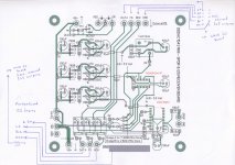
I have drawned the following general cabling diagram to explain my question:
An externally hosted image should be here but it was not working when we last tested it.
The WaveIO card I2S output should be linked to the 1543 card (I2S input).
My question is HOW should I connect the "V+" pin at the output of the WaveIO card ? It has to receive +5V, but can connect it to the +5V of the main WaveIO card (as on the attached diagram), or should I get this +5V from somewhere else ? (maybe the 1543 VB+ output ?)
I am not sure at all of my cabling, so I prefer to ask prior doing anything wrong ...
Thanks !
Also Im pretty sure the sowters primaries go across the pos and neg output from the dac board not the pos and com
OK my mistake, I have changed the cabling diagram accordingly...
use the V out from the 10 pin header on the mainboard. straight to the USB board
By the inputs of the Mainboard there is a 3.3v output pin normally that is connected to the WAVE I/O through the standard ribbon cable Doede supplies with the kit.
OK: The "V+" of the WaveIO I2S connector is provided by the "VDDout" of the Motherboard 10 pins header.
This VDDout is supposed to deliver +5V, not 3.3V as the pin located near the I2S inputs, so this last one should be useless if I understand correctly.
Thanks friends, for all these details, my cabling diagram should now be OK :

Please read the WAVEI/O documentation carefully. This voltage can be between 3.3v and 5v. 3.3v will work with no problem at all. There are many DDDAC boards using the same 3.3v output without any problems.
http://www.luckit.biz/downloads/WaveIO%20Infos.pdf See page 2 note: 5
http://www.luckit.biz/downloads/WaveIO%20Infos.pdf See page 2 note: 5
Last edited:
My DDDAC arrived yesterday, and Today I have it half essembled. Many thanks Doede!
Here to share my excitement with photos attached!


Sent from my iPad using Tapatalk
Here to share my excitement with photos attached!
An externally hosted image should be here but it was not working when we last tested it.
An externally hosted image should be here but it was not working when we last tested it.
An externally hosted image should be here but it was not working when we last tested it.
An externally hosted image should be here but it was not working when we last tested it.
An externally hosted image should be here but it was not working when we last tested it.
An externally hosted image should be here but it was not working when we last tested it.
Sent from my iPad using Tapatalk
Chanh,
congratulations... this is one of the best HiFi-investments in your life...
this is a five hundred horse power formula I machine...
and even if one is lucky to own a set like this there is an enourmos amount of work to be done to get these horse powers on to the road without squeeking...
anyway a "perfect" thing to start with...
would you be so kind and keep us informed about your listening experiences and progresses?
well, at the moment I am listening to the same (without the sowters), foobar and the foo_ram add, i.e. playing out of PC's own memory, and even if one thinks knowing already everything about digital stream, this is another step upwards and definitely a class on its own...
enjoy your weekend and your musical time ahead !!!
Hi rhlauranna,
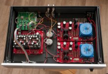
Many thanks! Mine came with a pair of Sowters! I have also went on replaced the stock 4700uf caps for 12V to DAC to Mundorf M-Lytic caps as shown on the photo. 4700uf stock caps for USB remain unchanged.
Furthermore, I was thinking of replace a 1uf cap on mainboard near Tent clock (pls see photo) to a better grade cap like Jensen copper or Mundorf SGO. Also want to add bypass cap 2.2uf Mundorf Supreme to 470uf electrolytic and 0.22uf Audyn true copper to 47uf electrolytic on the mainboard. An email to Doede if these are ok so I can start my experiment further the boundary of SQ!
Best,
Chanh
Sent from my iPad using Tapatalk
Many thanks! Mine came with a pair of Sowters! I have also went on replaced the stock 4700uf caps for 12V to DAC to Mundorf M-Lytic caps as shown on the photo. 4700uf stock caps for USB remain unchanged.
Furthermore, I was thinking of replace a 1uf cap on mainboard near Tent clock (pls see photo) to a better grade cap like Jensen copper or Mundorf SGO. Also want to add bypass cap 2.2uf Mundorf Supreme to 470uf electrolytic and 0.22uf Audyn true copper to 47uf electrolytic on the mainboard. An email to Doede if these are ok so I can start my experiment further the boundary of SQ!
An externally hosted image should be here but it was not working when we last tested it.
Best,
Chanh
Sent from my iPad using Tapatalk
Hi Chanh,
well, now you are able - at least to generate - frequencies which are produced for example by instruments like this and which very heavily define the whole sound, the transport and the reproducion of those are other chapters...
to give you an impression of what changes now for you simply from measurements done all at 1.000 cycles (an "easy" frequency, where everywhere in electronics the world is "o.k." and just "fine", and not an extreme one where the set definitely has to show what it is really capable of, but already here the differences are very very obvious), please have a look here at this picture which I got from Klaus just the other day showing Decca London Jubilee pick-up and Philips LHH 1000 CD Player
and here the results of Doede's genious masterpiece which speak for themselves at 1.000 cycles
and 20 cycles (and this is really incedible!!!)
this is as close to "perfection" as it gets... and it is rather easy: if you do not have these frequencies right in the beginning, you are not able to amplify and reproduce them, so, one of the biggest secrets in HiFi is to have/possess/generate a "perfect" input...
for more, have a look here:
DDDAC 1794 NOS DAC - Non Oversampling DAC with PCM1794 - no digital filter - modular design DIY DAC for high resolution audio 192/24 192kHz 24bit
...and the next step is to "amplify" this as is without adding or reducing anything...
enjoy
well, now you are able - at least to generate - frequencies which are produced for example by instruments like this and which very heavily define the whole sound, the transport and the reproducion of those are other chapters...
An externally hosted image should be here but it was not working when we last tested it.
to give you an impression of what changes now for you simply from measurements done all at 1.000 cycles (an "easy" frequency, where everywhere in electronics the world is "o.k." and just "fine", and not an extreme one where the set definitely has to show what it is really capable of, but already here the differences are very very obvious), please have a look here at this picture which I got from Klaus just the other day showing Decca London Jubilee pick-up and Philips LHH 1000 CD Player
An externally hosted image should be here but it was not working when we last tested it.
and here the results of Doede's genious masterpiece which speak for themselves at 1.000 cycles
An externally hosted image should be here but it was not working when we last tested it.
and 20 cycles (and this is really incedible!!!)
An externally hosted image should be here but it was not working when we last tested it.
this is as close to "perfection" as it gets... and it is rather easy: if you do not have these frequencies right in the beginning, you are not able to amplify and reproduce them, so, one of the biggest secrets in HiFi is to have/possess/generate a "perfect" input...
for more, have a look here:
DDDAC 1794 NOS DAC - Non Oversampling DAC with PCM1794 - no digital filter - modular design DIY DAC for high resolution audio 192/24 192kHz 24bit
...and the next step is to "amplify" this as is without adding or reducing anything...
enjoy
Last edited:
USB connections
I've just got my DDDAC working with a Wandboard running Squeezelite. I'm going to build the whole lot into one box and need to connect the usb out from the wandboard into the WaveIO. I therefore need a USB cable about 50mm long!!!
Any sugggestions how to connect them up?
cheers
Kev
I've just got my DDDAC working with a Wandboard running Squeezelite. I'm going to build the whole lot into one box and need to connect the usb out from the wandboard into the WaveIO. I therefore need a USB cable about 50mm long!!!
Any sugggestions how to connect them up?
cheers
Kev
Post 945 has the waveio pdf. The first item says:I've just got my DDDAC working with a Wandboard running Squeezelite. I'm going to build the whole lot into one box and need to connect the usb out from the wandboard into the WaveIO. I therefore need a USB cable about 50mm long!!!
Any sugggestions how to connect them up?
cheers
Kev
J1 - External USB
For the J8 (the one in top-left corner of the card
- near the USB-B on-board connector): EXT
means that USB data bus will be connected to the J1
external USB pin header while BRD
option will choose the on-board USB input. If there
's no jumper then BRD is selected by
default.
The J1 pinout is visible on the card:
SHD = USB shield,
GND = USB Ground,
DT+ and DT- are USB Data lines,
+5V = USB 5V VDD.
You could cut a regular usb cable and wire it to the header J1?
Last edited:
Post 945 has the waveio pdf. The first item says:
J1 - External USB
For the J8 (the one in top-left corner of the card
- near the USB-B on-board connector): EXT
means that USB data bus will be connected to the J1
external USB pin header while BRD
option will choose the on-board USB input. If there
's no jumper then BRD is selected by
default.
The J1 pinout is visible on the card:
SHD = USB shield,
GND = USB Ground,
DT+ and DT- are USB Data lines,
+5V = USB 5V VDD.
You could cut a regular usb cable and wire it to the header J1?
Excellent, thanks for that. I had to read it a couple of times before it sank in what it all meant.
I have the waveIO powered from an external supply so I assume I shouldn't connect the 5V line and ground, only the DT+ and -
Just done a google search and it appears that the wires I need are white and green, do you know if this is a universal colour scheme.
Sorry, I'm not a usb expert! However, usually the power cables are thicker than the signal ones. You could just use a pair of CAT-5E ethernet cable maybe? It's going to be a very short distance right? They are already twisted, just strip a short length of it and take one twisted pair? Use one of these at the motherboard end:I have the waveIO powered from an external supply so I assume I shouldn't connect the 5V line and ground, only the DT+ and -
Just done a google search and it appears that the wires I need are white and green, do you know if this is a universal colour scheme.
http://www.digikey.com/product-detail/en/A-USBPB-R/AE10178-ND/1119639
or one of these, whichever one you need
http://www.digikey.com/product-detail/en/A-USBPA-2-R/AE10637-ND/2170553
Please, anyone who knows better than me please chime in.
You do have to jumper the wave io to use the EXT usb connector, not the BRD one.
Last edited:
the new wiring diagram is perfectly okay. as you go for multiple boards, it is better to use the 5 volt connection as you drew...
Thanks very much Doede, so I start my last cabling phase...
I see that the new Mainboard can deal both with SPDIF and I2S (as announced): very good news, as I will probably build a second DAC for a friend of mine very soon !
After 3 hours of paper sand every leg of cap, resister,..., every components' legs going inside all boards and washed with Isopropyl Alcohol using cotton balls. I have finally done with all the soldering! Time to connect them together with a friend here to be schedule for final circuit checks and preliminary listening to it!
Sent from my iPhone using Tapatalk
An externally hosted image should be here but it was not working when we last tested it.
An externally hosted image should be here but it was not working when we last tested it.
Sent from my iPhone using Tapatalk
Many thanks rfthon! If you guys don't mind, I will keep uploading the progress photos?Nice work Chanh, I see you have the new main board.
Are the R-load resistors delivered with the package?
No, the IV resisters are those AudioNote Tantalum 18R for 8-decks which I bought separately on a recommendation from a good friend. I guess, am too paranoid with perfection despite knowing I will never get there.

There was one time I thought of replace all DAC resisters with either Shinko or AudioNote Tantalum but the invoice got too ridiculously expensive for little if any SQ gain. The stock from Doede are very decent already!
Best,
Chanh
- Home
- Source & Line
- Digital Line Level
- A NOS 192/24 DAC with the PCM1794 (and WaveIO USB input)