You just got to love this forum! I look forward to the feedback. I am very happy with my "vanilla" build though!
Doede, may I ask you where you have your TVC remote relay board from (Arduino based)? Is it open design? I am looking for a 23 relay remote board for my Silk transformers, currently operated by a Blore Edwards rotary switch. I prefer a proven solution over my own easyEDA brewings")
I posted a designs for a 23 step relay based TVC back in post #7747 that works well for me. I don’t have any spare boards remaining but they were cheap as chips from PCBWays a couple of years ago.
Not in the code that I posted though it is just a Simple Matter of Programming! I use an Ethernet board on the Arduino and an iPad app to control the volume/mute and input switching when they need to change. When no changes are needed, I don’t even power up the TVC controller because it uses latching relays that retain the volume and input selection.Thanks Doede and Kurand. I will have a look at the post with the schematics, PCBs and Arduino files. Looks to be very promising! Does it include code for remote control?
Audio Creative posted a nice story on a highly pimped DDDAC.
Here is the link
BerryStreamer XL Ultimo
It is in Dutch, but they have the google translate function on their website to translate into whatever language….
.
Here is the link
BerryStreamer XL Ultimo
It is in Dutch, but they have the google translate function on their website to translate into whatever language….
.
Last edited:
Ladies and gentlemen i present to you a mini dddac measuring just 160x140mm.
I want to metion that this is not for sale, only for me as this is my hobby.
Specs:
-single board, upgradeable to dual board and cinemag cmli 15/15b
-jumpers for transformer load resistor and xlr ground are included
-currenty using 4 10uF polyester capacitors for balanced output
-dual (for 2 board) vishay dale 0.05% 135ohm IV resistors
-silmic ii analog capacitors, oscon for everything else
-improved tent shunt as close to dac as possible
-68nf film pps capacitors directly at dac pins
-for 3.3V and 5V i used ADP7142, 11uV of noise
-no UA7810 or similar preregulation, main power supply is regulated with
soft start
-for ccs i used 2SK208-R, hand picked according to IDSS measurment
-with or without digital i2s buffer (few jumpers selection)
-al digital logic chips are in a small TSSOP package
-usb input only
-rca and xlr output
-for usb to i2s i used XMOS board with cpld reclocking
-semi toroidal power supply transformer used for minimal primary to
secondacy capacitance
-"golden reference" power supply by Kevin Gilmore. Used in Headamp GSX
mini headphone amp. Tottaly inverting diode switching noise and max 1uV
of noise at nominal load.
-in power supply there is only one heat source (transistor) which will be
scwered to bottom part of the case
-i will drill and engrave my case with cnc
-everything is handsoldered as im a 23yo with extremely good eyesight and
steady hands
Anyway, it sounds very very effortless. With lots of detail. I never heard such natural voices. Soundstage is very spaceous, so much that i occasionally think there is someone in the room. Bass is very deep and full but not bloated. I use 10uF capacitors because of my headphone amp input impedance (10k). For now i only had a chance to test single ended capacitor output. Dac is absolutely quiet.
Pcb is designed by me. It gets comfortably warm at the dac area.
I hope you like it.
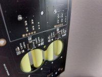
PICTURES:
Update your browser to use Google Drive, Docs, Sheets, Sites, Slides, and Forms - Google Drive Help
Julio
I want to metion that this is not for sale, only for me as this is my hobby.
Specs:
-single board, upgradeable to dual board and cinemag cmli 15/15b
-jumpers for transformer load resistor and xlr ground are included
-currenty using 4 10uF polyester capacitors for balanced output
-dual (for 2 board) vishay dale 0.05% 135ohm IV resistors
-silmic ii analog capacitors, oscon for everything else
-improved tent shunt as close to dac as possible
-68nf film pps capacitors directly at dac pins
-for 3.3V and 5V i used ADP7142, 11uV of noise
-no UA7810 or similar preregulation, main power supply is regulated with
soft start
-for ccs i used 2SK208-R, hand picked according to IDSS measurment
-with or without digital i2s buffer (few jumpers selection)
-al digital logic chips are in a small TSSOP package
-usb input only
-rca and xlr output
-for usb to i2s i used XMOS board with cpld reclocking
-semi toroidal power supply transformer used for minimal primary to
secondacy capacitance
-"golden reference" power supply by Kevin Gilmore. Used in Headamp GSX
mini headphone amp. Tottaly inverting diode switching noise and max 1uV
of noise at nominal load.
-in power supply there is only one heat source (transistor) which will be
scwered to bottom part of the case
-i will drill and engrave my case with cnc
-everything is handsoldered as im a 23yo with extremely good eyesight and
steady hands
Anyway, it sounds very very effortless. With lots of detail. I never heard such natural voices. Soundstage is very spaceous, so much that i occasionally think there is someone in the room. Bass is very deep and full but not bloated. I use 10uF capacitors because of my headphone amp input impedance (10k). For now i only had a chance to test single ended capacitor output. Dac is absolutely quiet.
Pcb is designed by me. It gets comfortably warm at the dac area.
I hope you like it.
PICTURES:
Update your browser to use Google Drive, Docs, Sheets, Sites, Slides, and Forms - Google Drive Help
Julio
You packed it extremely well, congratulations. With one DAC PCB there is no chance to put a transformer at the output without some buffer, with two parallel ones maybe you can. Only if Ivan doesn't have a solution with a custom transformer for that as well. As for the tubes at the exit, since you already asked me once, it means that it is a sound coloring device. Maybe you can get good results with Broskie Cathode Follower, but I haven't had a chance to hear it anywhere yet. In that case there is no balanced output, only single ended. There is also an option with an balanced operational amplifier, where you would avoid coupling capacitors and null output DC voltage, for example OPA1632. For balanced to unbalanced conversion, you can use for example OPA1612. Of course, the sound with OPA is completely different than with other options, so you should try it all first, then decide on the best variant. Those trials also cost some money and time.
A better result than OPA alone can be obtained by adding a mosfet source follower that is included in the NFB at the OPA output. This forces OPA to work in class A and SE mode, and that sounds more humane than just OPA. I used an IRF510 with OPA1612 in one preamplifier. IRF510 is good for this purpose due to the small input capacitance. The output impedance from the source follower is very small, a few ohms, depending on the current through the mosfet, and can drive even low-impedance headphones.
A better result than OPA alone can be obtained by adding a mosfet source follower that is included in the NFB at the OPA output. This forces OPA to work in class A and SE mode, and that sounds more humane than just OPA. I used an IRF510 with OPA1612 in one preamplifier. IRF510 is good for this purpose due to the small input capacitance. The output impedance from the source follower is very small, a few ohms, depending on the current through the mosfet, and can drive even low-impedance headphones.
Last edited:
Thanks man. I just left space for transfomers but im very satisfied with capacitors. I hope that i could try transformers before buying them one day. As i am mainly using headphones i will have a tube amp for that tube magic.
I will upgrade to dual board anyway as it costs me no more than 50euro including pcb and parts
I actually put a OPA1632 summer and buffer on the other side of the pcb. It could be used for balanced or single ended output. I can completely remove opamp with few jumpers. It works fine, but imo it is too bright and it loses that NOS magic and soundstage. So capacitor it is.
Thanks for the usefull advices. I will experiment.
Attachments
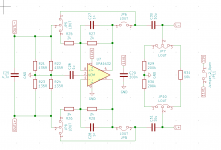
So you already have a buffer with OPA1632. I would definitely try a 1:1 transformer on that output. The transformer also colors the sound, you just need to find one that does it well. Add another DAC PCB, it will sound better.
And just to add, I don't think you need an output capacitor on the OPA1632, it's a low offset OPA. Check the DC offset, on the OPA1612 it is only 0.1-0.2mV. Even if it's bigger, a couple of mV, it can't cause any problems.
And just to add, I don't think you need an output capacitor on the OPA1632, it's a low offset OPA. Check the DC offset, on the OPA1612 it is only 0.1-0.2mV. Even if it's bigger, a couple of mV, it can't cause any problems.
Last edited:
When you add another DAC PCB, you can think of a transformer directly to the DAC outputs. I am currently using a custom made transformer. I found some old but very high quality Mumetal EI core, my good friend wound bifilar primary and secondary, and I really like it. I have a few of these cores, and I'll be trying a few more thicknesses of wire in the primary and secondary soon, and I probably won't go any further.
Am I the only one who gets the best sound at 7.5V on analog side? I find 8.2V too bright and too focused with lack of bass quantity. At 7.5V focus is not so up close and voices and instruments become much more defined in space.
The soundstage is crazy good at 7.5V. I hear guitar "10 meters" away. I literally can tell of how thick wood guitar is made of.
I don't know... maybe it's only my amp and headphones that make the difference.
The soundstage is crazy good at 7.5V. I hear guitar "10 meters" away. I literally can tell of how thick wood guitar is made of.
I don't know... maybe it's only my amp and headphones that make the difference.
I guess you will not find that many people who have compared different analog voltage levels. I would try it, because I'm curious if I could hear any differences, but especially with the new DAC boards it's not that easy to change the voltage (because of the tent shunt part). And I think that doede with his experience has chosen the correct voltage carefully during design phase! I don't find any lack of bass with my DDDAC either. I remember that the input voltage for the shunt and the LDO in front is important and that exact 12V may be a little bit too low. There was 12,5V recommended. I'm also running it with a little bit higher input voltage. So maybe you get a better performance by decreasing the analog (output) voltage, because the working voltage for the LDO / Tent shunt is higher in that case?
By the way, I have received the Sowter TVC version (Thanks Doede!), running it with an arduino / relay controller and directly driving my power amp. It's not cheap, but it’s worth the money in my opinion. I can only recommend. I'm waiting for some additional parts for the FifoPi section. I then want to finish my DDDAC and put it into a case. Will share it once it is finished.
By the way, I have received the Sowter TVC version (Thanks Doede!), running it with an arduino / relay controller and directly driving my power amp. It's not cheap, but it’s worth the money in my opinion. I can only recommend. I'm waiting for some additional parts for the FifoPi section. I then want to finish my DDDAC and put it into a case. Will share it once it is finished.
- Home
- Source & Line
- Digital Line Level
- A NOS 192/24 DAC with the PCM1794 (and WaveIO USB input)