I also have the j502 and that jfet you mentioned before to to try with the 5 to 10k r yet
How do I measure the current sink of the jfet sink?
I don't think my meter can read that low
Is it possible that there might be an optimum current draw ie 0.30ma
Might be worth bearing in mind what the draw is with the sinks were comparing
How do I measure the current sink of the jfet sink?
I don't think my meter can read that low
Is it possible that there might be an optimum current draw ie 0.30ma
Might be worth bearing in mind what the draw is with the sinks were comparing
Well I knew the data sheet 10k was .24 ma and deode recommends .4 ma the rest was a lack of options
After putting the j502 in the left channel the e301 is in the right
Dunno which is better yet
The dacs a different beast really giving the drivers a bit of a workout
loads of movement
After putting the j502 in the left channel the e301 is in the right
Dunno which is better yet
The dacs a different beast really giving the drivers a bit of a workout
loads of movement
I also have the j502 and that jfet you mentioned before to to try with the 5 to 10k r yet
How do I measure the current sink of the jfet sink?
I don't think my meter can read that low
Is it possible that there might be an optimum current draw ie 0.30ma
Might be worth bearing in mind what the draw is with the sinks were comparing
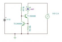
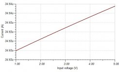
you simply build the CCS separately and put it in series with a resistor that would drop a voltage comfortably measurable with your DMM. For instance, for 400uA, a 10k resistor in series would tell you that your CCS is adjusted if that resistor drops 4V. Obviously, that wouldn't be possible if you supply the test setup with 2.4V - go for feasibly more. To state the obvious, you adjust the CCS by varying Rset until you get the desired value.
BTW - if you leave the pot there (Rset) instead of replacing it with a fixed value for what gets 400uA through the CCS, you can listen to various currents and stick to the optimum by ear. We'd be interested in what that current is... Be careful to wild variations, though, I suggest limiting your range with a fixed resistor in series with the pot.
Ahh yes, now I have a look at what's actually easily available, 0.3mA looks like a great choiceWell I knew the data sheet 10k was .24 ma and deode recommends .4 ma the rest was a lack of options
After putting the j502 in the left channel the e301 is in the right
Dunno which is better yet
The dacs a different beast really giving the drivers a bit of a workout
loads of movement
")
you simply build the CCS separately and put it in series with a resistor that would drop a voltage comfortably measurable with your DMM. For instance, for 400uA, a 10k resistor in series would tell you that your CCS is adjusted if that resistor drops 4V. Obviously, that wouldn't be possible if you supply the test setup with 2.4V - go for feasibly more. To state the obvious, you adjust the CCS by varying Rset until you get the desired value.
BTW - if you leave the pot there (Rset) instead of replacing it with a fixed value for what gets 400uA through the CCS, you can listen to various currents and stick to the optimum by ear. We'd be interested in what that current is... Be careful to wild variations, though, I suggest limiting your range with a fixed resistor in series with the pot.
Cool thx
Tbh I've tested different r values didn't think there was much in it
Was wondering with the voltage swings would it have impact on the current draw on pin 20
Maybe the resistors can't maintain the current draw as well as the diodes
Sent from my iPad using Tapatalk
http://www.micross.com/pdf/LSM_J502_TO-92.pdf
Just reading that current range on the J502 is +/-20%. I was hoping since the spec is in mA two digits after the comma, it was more accurate.
The E-301 seems to be about the same..
Just reading that current range on the J502 is +/-20%. I was hoping since the spec is in mA two digits after the comma, it was more accurate.
The E-301 seems to be about the same..
http://www.micross.com/pdf/LSM_J502_TO-92.pdf
Just reading that current range on the J502 is +/-20%. I was hoping since the spec is in mA two digits after the comma, it was more accurate.
The E-301 seems to be about the same..
Whats the current range of pin 20 and resistor?
diodes were for a quick test only
though it would seem they should be an option too
I could be wrong but I would imagine that this is not operating tolerance, but manufacturing tolerance. The same as it is with buying resistors. So a 0.1% resistor can be practically identical to a 1% resistor of the same make in terms of being stable at whatever resistance it happens to be, it just means they have been measured and selected in the factory to be more accurately close to the advertised rating.http://www.micross.com/pdf/LSM_J502_TO-92.pdf
Just reading that current range on the J502 is +/-20%. I was hoping since the spec is in mA two digits after the comma, it was more accurate.
The E-301 seems to be about the same..
I think these current regulator diodes will regulate quite accurately, just not necessarily at the precise current stated. I also imagine stating +-20% is them really playing it safe and a real world test would be much more accurate.
Maybe you need to buy a handful of these JFETs and measure and select a closely matched pair?
Nige, did you measure yours by any chance?
I could be wrong but I would imagine that this is not operating tolerance, but manufacturing tolerance. The same as it is with buying resistors. So a 0.1% resistor can be practically identical to a 1% resistor of the same make in terms of being stable at whatever resistance it happens to be, it just means they have been measured and selected in the factory to be more accurately close to the advertised rating.
I think these current regulator diodes will regulate quite accurately, just not necessarily at the precise current stated. I also imagine stating +-20% is them really playing it safe and a real world test would be much more accurate.
Maybe you need to buy a handful of these JFETs and measure and select a closely matched pair?
Nige, did you measure yours by any chance?
Nope measured nothing yet
I basically fired one in listened for 5 sec
Thought wtf then fired the other one in last night
Listened for a 20 min this morning
Fairly conclusive everything better especially bass
I'm nearly inclined to assume that the actual current draw probably doesn't matter much well within reason as long as it's constant
But then again assuming isn't knowing so it will need to be tested
Yea I'd imagine the + or - tolerance is on the diodes current draw not its current stability
finally more insight!!! great job
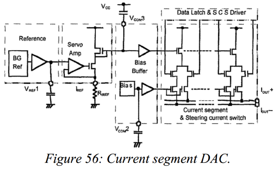
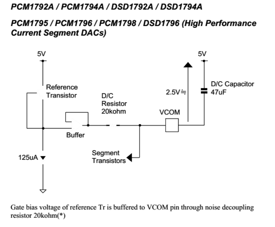
I like to "study" this a bit to get my thoughts around the concept and tweak options. it make sense now, the 47 uF and 20k is indeed the one second time the dac is starting up at DC bias...
one little warning on the current diodes....
Pin 20 bias is defining the output DC bias. together with the Rload resistors this give the D. working point as well the AC working point.
therefore I would like to know now what DC voltage you see at the POS and NEG terminal versus common and also what Rload you are using right now, as you had this special set up with the extra resistors....
just throwing in any current can cause the DC and AC working point to be wrong and cause extra distortion...
finally more insight!!! great job
I like to "study" this a bit to get my thoughts around the concept and tweak options. it make sense now, the 47 uF and 20k is indeed the one second time the dac is starting up at DC bias...
one little warning on the current diodes....
Pin 20 bias is defining the output DC bias. together with the Rload resistors this give the D. working point as well the AC working point.
therefore I would like to know now what DC voltage you see at the POS and NEG terminal versus common and also what Rload you are using right now, as you had this special set up with the extra resistors....
just throwing in any current can cause the DC and AC working point to be wrong and cause extra distortion...
dont know how i didnt notice that before
ive got the j502 (400uA) in the left and the e301 (300uA)in the right channel
im testing an rload of 39r+10r atm
left channel is approx 1v between pos/neg and gnd right is 2.4v
co-incidence i didnt have 300+rload
things just got more complicated
however the j502 sounded much better than the 6k1 so at least thats a like with like comparison
Last edited:
I. think we need to test this with the standard configuration with single ended output with standard Rload. That should be the starting point...
how many decks do you run?
std config as in 400uA iref 133r iv r's etc etc?
ill try get the jfet sink set to 400uA
- Home
- Source & Line
- Digital Line Level
- A NOS 192/24 DAC with the PCM1794 (and WaveIO USB input)