If something is to be repeatedly plugged and unplugged then conversion to some other standard with defined impedance and robust plugs/sockets is best. I2S is intended to get digital signals from one chip to a near neighbour on the same board. Maybe the right answer is that 10cm to another board is not what I2S is intended for, so it might not work too well. AES/SPDIF is the standard for longer distances.
10cm should be just fine, the only fast signal is the Mclk, and that does not need to have a defined phase relationship with the other signals (as long as it is constant), so a source terminated coax to a high Z input would probably be fine for that with the rest on a bit of ribbon.
But in a more general sense, yea, at least turn it into something like LVDS that actually does carry a reasonable distance, cmos to and from LVDS converters are off the shelf and get you a defined impedance and differential signalling.
AES is the right answer if you need a single pair with embedded clock and no DC component, but is probably the wrong tool inside equipment.
Regards, Dan.
Very interesting discussion - certainly great to have all the theory in one thread. I2S is more prevalent & topical now than ever.
In relation to this particular implementation - I've found some 6-conductor ribbon cable at Element 14 which should work fine - the key question then becomes; if we are using ribbon cable or simple coax, what will be the optimal distance between the pcbs? The two pcbs were barely $30 each so I think I'll get it functional prior to trying some more expensive cable.
In relation to this particular implementation - I've found some 6-conductor ribbon cable at Element 14 which should work fine - the key question then becomes; if we are using ribbon cable or simple coax, what will be the optimal distance between the pcbs? The two pcbs were barely $30 each so I think I'll get it functional prior to trying some more expensive cable.
Last edited:
no I meant what I said, you just misread me, perhaps I needed a paragraph break in there between sentences to reinforce I was talking about 2 different forces. I dont mean the return current travels through the air, just that noise resulting from the HF signal can easily become airbourne if you dont have a return path nearby. these are radiated noise currents (I guess they are still called currents?) generated by the HF and high slewrate signal interacting with the surrounding components via electromagnetic coupling
marce explained it better than me of course, but I wasnt saying that the signal would spontaneously leave the wire, not even quite sure what you are thinking I was trying to say TBH =) but I freely admit this whole subatomic wavelet soup hurts my head to think about.
I knew what you meant, I just wasn't sure that everyone reading it would
")
A beginner could easily read the below as meaning the electron current path is via the air, which we know isn't the case. That was all I was pointing out.
i2s signals, particularly MCLK are quite high frequency, they are up in the radio frequency bands. high frequencies/radio frequencies travel quite well through the air, as you know, because the air presents a low impedance at high frequencies, so if there is no lower impedance path nearby, it will just find its own way through the air to the nearest ground or signal trace or component in a fairly unpredictable way.
I've added emphasis to the parts I was concerned could mislead others.
I know I'm being a pedantic assh*le, just trying to avoid any more confusion than necessary on these topics.
Chris
Coax for this is iffy, I2C does not usually have a well defined impedance, and usually expects to see a full level swing at the recever, both of which argue aagainst a transmission line treatment.
Regards, Dan.
Dan,
Could you elaborate on why these elements argue against transmission line treatment please? Especially the part about full level swing. I work in elec distribution so the details of these systems are hobby only for me and something I am happy to admit I am far from 100% on.
Chris
As close as possible? Given that I2S is not a controlled impedance interface, the shorter the better.
you keep saying that, yet all the PCBs i'm using are using a controlled impedance and the clock, clock buffer and dac side are all controlling the impedance in one way or another and using terminated lines that gel with that.
the datasheets for the high speed potato logic gates call for it, the buffers etc are all running at high speed, not just frequency, but rise time and they call for terminated lines too. the MCLK is running up to 100MHz and the logic parts are very fast indeed, so they should make some attempt to control these conditions IMO. just saying i2s isnt a controlled impedance and isnt high speed kinda misses a lot of factors in todays hardware
what I meant by length is just keeping something short doesnt stop reflections. i'm not saying that short isnt good, of course it is and efforts should be made to keep it so if possible, but I dont think just keeping it short is going to help all that much if there are other problems going on in the solder joints, connectors, wire pitch, wire dielectric etc etc.
now that the level of investment has been revealed, i'm going to side with you anyway, use the ribbon lordearl, its easy, not ideal but its decent and I gather at those prices its probably not running a high speed clock, as these are usually custom.
Last edited:
A transmission line will normally need the same source and load impedance. These act as a potential divider so the receiver only sees half the voltage sent by the transmitter. Drivers and receivers designed for this can cope, but normal digital interfaces expect to see roughly the same voltage at each end. This means a load impedance which is significantly higher than the source impedance, so any transmission line will be misterminated. This means it has to be short, but reflections can be reduced by using some degree of back-termination: series resistors at the sending end. These will be lower than the line characteristic impedance so don't fully terminate it but do attenuate reflections.
Given suitable line drivers and receivers, there is no reason why I2S protocol should not be used on a transmission line. The bare digital ports on audio chips don't seem to define an impedance, so they appear to be intended for short connections where reflections are not a major problem because the time delay is so short. However, this would require rise times which are not too short either.
Given suitable line drivers and receivers, there is no reason why I2S protocol should not be used on a transmission line. The bare digital ports on audio chips don't seem to define an impedance, so they appear to be intended for short connections where reflections are not a major problem because the time delay is so short. However, this would require rise times which are not too short either.
Last edited:
Dan,
Could you elaborate on why these elements argue against transmission line treatment please? Especially the part about full level swing. I work in elec distribution so the details of these systems are hobby only for me and something I am happy to admit I am far from 100% on.
Chris
I would think because the impedance and maybe termination causes some voltage drop, thus not full swing is received.
100% haha when does that happen?
I2S is a flavour of the serial peripheral interfaces that are becoming more common for inter device communication, very similar to I2C. When the IBIS models of the various drives are compared they are basically the same, some Ti codecs have both interfaces.
All of these should be laid out in daisy chain fashion where more than one device is used and as a bus, i.e. all signals together. We see more problems with these types of buses than a lot of others as quite often they are routed as separate signals all over the place.
Transmission line rules apply to these and we will sometimes simulate them using the signal integrity verification software. Numerous reasons why, one of the main being, if you look at the IBIS data for a lot of serial drivers they are quite low impedance with quite a strong current output, so often the signals will have quite a few reflections. Using the simulation software allows us to calculate the values of any termination required to match the PCB characteristic impedance.
Standard PCB impedances for digital signals are usually between 50-100Ohm, depending on thickness of copper, trace width and distance from return signal plane. You can use this:
Saturn PCB Design - PCB Via Current | PCB Trace Width | Differential Pair Calculator | PCB Impedance
to do some rough and ready impedance calculations. For the simulation software there is a full 3D field solver that does a much more accurate job, though you do have to detail your PCB stack up with thickness of all layers and the materials used for the pre-pregs and laminates (we have a data base of all the common current laminates available that we use).
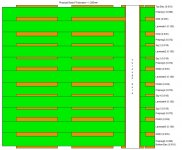
An example of a 12 layer stack up attached below. Only about 35% of the designs I do are actually controlled impedance boards, his is due to the increased manufacturing costs mainly, as you are adding 15-25% to the cost of each PCB, depending whether you want the value controlled to 10% standard or 5%. The rest, are standard boards, where your impedances will be within 20-25% of your desired impedances. For a true controlled impedance PCB the manufacturer has to do a test coupon for every panel and measure the impedance of every test coupon before the boards can be released. The main breakpoint for companies to consider both controlled impedance designs and simulation at the moment is when they start to use DDR memory interfaces (even then a lot don’t, due to costs). But with the ever increasing rise time of todays devices, signal integrity is becoming more critical for even the most basic circuits. As said we are seeing more request for simulation on common busses that aren’t considered as high speed but are critical, these being JTAG clocks and sometimes the full JTAG bus, SPI in its many guises and clocks in general, even down to 12MHz clocks.
Most people look at the clock frequencies on a design and use these to determine whether a design is high speed, WRONG. As Dr Howard Johnson points out in his literature and seminars, high speed is determined by the rise time of the signals on your board, and t is the Knee frequency that determines the spectral content you have to cater for.
Instead of me rabbiting on about PCB impedance here is a link to Polar Instruments site:
PCB signal integrity and controlled impedance – PCB troubleshooting
When we do controlled impedance designs we work closely with the manufacturer, who use the polar tools to help work out our required PCB stack up, the laminates to use and the thickness of these laminates. We then enter this information into the PCB design layer stack up so that the simulation software is working on the correct data.
Again to get a full understanding of the issues, read and study any information (and books) from the likes of:
Dr Eric Bogatin: beTheSignal.com
Dr Howard Johnson: Signal Consulting, Inc. - Dr. Howard Johnson
Henry Ott: home page
Lee Richley: Right the First Time, A Practical Handbook on High-Speed PCB and System Design is now available
And this book is a good read with numerous stack up examples:
Charles Pfeil: Leading Successful BGA Design Solutions - Mentor Graphics
you can download a free PDF version.
Its only a brief look at the fun all this is, to put it into context of system etc, I have over £50K worth of software at my disposal, with the basic schematic and PCB packages, with constraints manager, high speed routing tools, simulation software for both signal integrity and power deliver system (both ac and dc simulations), EMC adviser, thermal and a full 3D CAD system (Inventor) for making sure everything fits in the box, and very liitle sleep!
Last point, if we dont use transmission line theory what do we use!I,m puzzled on that one as in over 25 years of playing about with high speed PCb design (VME, ecl etc in the 80s) I've always used transmission linetheory and calculators etc.
All of these should be laid out in daisy chain fashion where more than one device is used and as a bus, i.e. all signals together. We see more problems with these types of buses than a lot of others as quite often they are routed as separate signals all over the place.
Transmission line rules apply to these and we will sometimes simulate them using the signal integrity verification software. Numerous reasons why, one of the main being, if you look at the IBIS data for a lot of serial drivers they are quite low impedance with quite a strong current output, so often the signals will have quite a few reflections. Using the simulation software allows us to calculate the values of any termination required to match the PCB characteristic impedance.
Standard PCB impedances for digital signals are usually between 50-100Ohm, depending on thickness of copper, trace width and distance from return signal plane. You can use this:
Saturn PCB Design - PCB Via Current | PCB Trace Width | Differential Pair Calculator | PCB Impedance
to do some rough and ready impedance calculations. For the simulation software there is a full 3D field solver that does a much more accurate job, though you do have to detail your PCB stack up with thickness of all layers and the materials used for the pre-pregs and laminates (we have a data base of all the common current laminates available that we use).
An example of a 12 layer stack up attached below. Only about 35% of the designs I do are actually controlled impedance boards, his is due to the increased manufacturing costs mainly, as you are adding 15-25% to the cost of each PCB, depending whether you want the value controlled to 10% standard or 5%. The rest, are standard boards, where your impedances will be within 20-25% of your desired impedances. For a true controlled impedance PCB the manufacturer has to do a test coupon for every panel and measure the impedance of every test coupon before the boards can be released. The main breakpoint for companies to consider both controlled impedance designs and simulation at the moment is when they start to use DDR memory interfaces (even then a lot don’t, due to costs). But with the ever increasing rise time of todays devices, signal integrity is becoming more critical for even the most basic circuits. As said we are seeing more request for simulation on common busses that aren’t considered as high speed but are critical, these being JTAG clocks and sometimes the full JTAG bus, SPI in its many guises and clocks in general, even down to 12MHz clocks.
Most people look at the clock frequencies on a design and use these to determine whether a design is high speed, WRONG. As Dr Howard Johnson points out in his literature and seminars, high speed is determined by the rise time of the signals on your board, and t is the Knee frequency that determines the spectral content you have to cater for.
Instead of me rabbiting on about PCB impedance here is a link to Polar Instruments site:
PCB signal integrity and controlled impedance – PCB troubleshooting
When we do controlled impedance designs we work closely with the manufacturer, who use the polar tools to help work out our required PCB stack up, the laminates to use and the thickness of these laminates. We then enter this information into the PCB design layer stack up so that the simulation software is working on the correct data.
Again to get a full understanding of the issues, read and study any information (and books) from the likes of:
Dr Eric Bogatin: beTheSignal.com
Dr Howard Johnson: Signal Consulting, Inc. - Dr. Howard Johnson
Henry Ott: home page
Lee Richley: Right the First Time, A Practical Handbook on High-Speed PCB and System Design is now available
And this book is a good read with numerous stack up examples:
Charles Pfeil: Leading Successful BGA Design Solutions - Mentor Graphics
you can download a free PDF version.
Its only a brief look at the fun all this is, to put it into context of system etc, I have over £50K worth of software at my disposal, with the basic schematic and PCB packages, with constraints manager, high speed routing tools, simulation software for both signal integrity and power deliver system (both ac and dc simulations), EMC adviser, thermal and a full 3D CAD system (Inventor) for making sure everything fits in the box, and very liitle sleep!
Last point, if we dont use transmission line theory what do we use!I,m puzzled on that one as in over 25 years of playing about with high speed PCb design (VME, ecl etc in the 80s
) I've always used transmission linetheory and calculators etc.Attachments
What are the chosen impedances? While I2S doesn't specify a value a de facto standard would be helpful for letting DIY modules work better together. I've defaulted to 120 ohms as that's natural for low cost two layer PCBs, routes decently with 0.5mm pitch packages, and not too difficult to find in ribbon cable.all the PCBs i'm using are using a controlled impedance
Matching the drive to the PCB impedance is what is critical for ultimate signal integrity., these serial buses are designed to work on a variety of PCBs with differing impedances so generally you have a low output drive impedance and a higher input impedance
There is a lot of documentation regarding the i2c bus that is relevant to i2s, including information for taking the uses over CAT 5 twisted pair cable.
Two layer with digital is OK, if you can get a good contigous ground plane on the bottom layer.
There is a lot of documentation regarding the i2c bus that is relevant to i2s, including information for taking the uses over CAT 5 twisted pair cable.
Two layer with digital is OK, if you can get a good contigous ground plane on the bottom layer.
Ethernets 100 Ohms is for differential pair, single ended signals are 50 Ohm, when we do a controlled impedance board these are the figures we require (for the majority of signals), the high speed routing engine will change the track width as you change layers to keep the impedance constant.
As said a lot of these devices are desihgned to work under all conditions, and one of the beauties of digital it does work well on most designs, we very rarely see problems with most standard digital, its as I said earlier when DDR, gigabit ethernet and the LVDS serial interfaces that clock along at silly speeds come along we see problems where simulation and checking the layout has not been done (often for cost, cheep PC motherboards)
As said a lot of these devices are desihgned to work under all conditions, and one of the beauties of digital it does work well on most designs, we very rarely see problems with most standard digital, its as I said earlier when DDR, gigabit ethernet and the LVDS serial interfaces that clock along at silly speeds come along we see problems where simulation and checking the layout has not been done (often for cost, cheep PC motherboards
)Matching the drive to the PCB impedance is what is critical for ultimate signal integrity., these serial buses are designed to work on a variety of PCBs with differing impedances so generally you have a low output drive impedance and a higher input impedance
There is a lot of documentation regarding the i2c bus that is relevant to i2s, including information for taking the uses over CAT 5 twisted pair cable.
Two layer with digital is OK, if you can get a good contigous ground plane on the bottom layer.
I can hardly believe that you are lumping I2S together with I2C, they are completely different! I2S is point-to-point, and I2C is a multi-device bus. I2C uses open-collector drivers and pull-up resistors and has a signalling rate of 100 kHz, 400 kHz or a max of 3.4 MHz. The pull-ups are always well over 1 kΩ and sometimes much higher, so any talk of controlled impedance for I2C is almost humorous. I2S has completely different electrical characteristics, and as far as I can tell, any documentation or knowledge concerning implenting I2C is not applicable to I2S. The only exception I can see is when referring to specialized long-range I2C transmitters/receivers, which due to the necessity of long distance transmission, use transmission line theory complete with controlled impedance drivers, cables, and terminations. All of that is completely foreign to 'normal' I2C.
With that said, you obviously know what you are talking about w.r.t. controlled impedance PCB design. I think that the big unanswered (and remarkably, unasked!) question here is: What is the characteristic impedance of the I2S signal traces on the two PCBs that are being connected together?. That, of course, will determine what the characteristic impedance of the interconnect cabling should be. If these boards are DIY or designed by non-pros, then they may not have been designed to any specific impedance at all! It should be possible to calculate the impedance using the geometries of the PCBs (trace width, distance to ground, etc.) or measured by TDR techniques if the traces are long enough and a high speed scope is available.
Last edited:
I think 50 ohms is probably a non-starter---that's a ~93 mil trace for two layer FR4 62 mil boards, which is painfully fat. If one's doing a long haul it would make sense to put down LVDS PHYs but I2S directly over Ethernet patch cables has its attractions for sort haul.Ethernets 100 Ohms is for differential pair, single ended signals are 50 Ohm
Agree. Hence the suggestion of establishing a de facto standard.I think that the big unanswered (and remarkably, unasked!) question here is: What is the characteristic impedance of the I2S signal traces on the two PCBs that are being connected together?
Yeah, there's a reason Intel does the sims, publishes layout guidelines, and provides reference designs. But sometimes copying them is too hard.we see problems where simulation and checking the layout has not been done (often for cost, cheep PC motherboards
(Though, in fairness, I've never checked to see if other chipset vendors do the same, though I'd expect they'd have to in order to be competitive...)
Last edited:
My bad, I though i2s was a derivitive of i2c. We see i2c on nearly every job these days, and recently it was used as the go between between several Ti 320 series codecs, the multipoint must be why that was used and not the i2s pins on the devices.
The saturn toolkit will give a quick impedance calc based on basic geomatry, use that a lot for determining basic track widths when we are not gonna use the high speed stuff.
For normal baords the width tolerance is usually +/-10%.
Again I was mistaken about the similarities between the two buses, I will study the I2s spec in more detail.
In regards to your question, what happens if the boards have differing impedances? if the same then there is no problem, but say connecting a DIY board to a proffesionaly manufactured one there could be quite a difference.
Cheers, like lots here I am still learning and stand corrected
Most commercial digital baords are a minimum of four layers, when you have a DDR interfaces usually six is the minimum and often 8-14 layers are empoloyed as well as multiple power pairs, the proliferation of BGA devices require more layers just to get the traces out of the device. Though as youve pointed out for a two layer board the width is silly, a 12 mil (0.3mm) trace give about 120 ohm as you suggested, interesting though if you do a 4 layer board with three equal cores (roughly 0.5mm each), my calculater give a trace width of 3mil to achieve the same impedance!
Most devices now have layout guides, some of Xylinz's are huge, though the Intel spec for DDR interface is not a light read. Where possible we follow the guidlines given ro use a reference design for some guidance, no point re-inventing the wheel.
Most devices now have layout guides, some of Xylinz's are huge, though the Intel spec for DDR interface is not a light read. Where possible we follow the guidlines given ro use a reference design for some guidance, no point re-inventing the wheel.
Yeah, there's probably not a good way to choose an impedance value that works for both two and four layers on low cost boards, especially if the four layer is EMI optimized and has close outer spacings in the SPGS stackup.
However, I've yet to see a four layer board used in a dedicated audio application; every DIY candidate I've taken apart or looked at closely on the 'net has been two layer. That's not to say there aren't 4+ layer boards out there carrying audio---there's of course a plethora of PCs, phones, and so on---just that it seems a de facto impedance standard aimed at two layer would cover the majority of cases where a DIYer would want to integrate different modules using I2S.
However, I've yet to see a four layer board used in a dedicated audio application; every DIY candidate I've taken apart or looked at closely on the 'net has been two layer. That's not to say there aren't 4+ layer boards out there carrying audio---there's of course a plethora of PCs, phones, and so on---just that it seems a de facto impedance standard aimed at two layer would cover the majority of cases where a DIYer would want to integrate different modules using I2S.
Last edited:
- Status
- This old topic is closed. If you want to reopen this topic, contact a moderator using the "Report Post" button.
- Home
- Source & Line
- Digital Line Level
- i2s cable/wire type