I am using a DEQ 2496 in my HT/ Stereo/ Sound system for synthesizers with importance in that order.
I use the Toslink input from my Satellite receiver and this works well.
The peak holding input meter shows between -5 and -7 dBFS when I store the peak over a few TV episodes with have some very loud effects and a full length movie.(NCIS, Bones, 30 Rock, the Mentalist and Avatar).
I am using the AES/EBU input from a DVD Player/Burner that plays CD's.
.
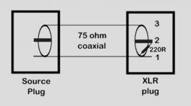
I made an RCA to XLR cable with a 220 ohm resistor between pin 1 and pin 3 of the XLR.
I was following the instructions in the article Using the Behringer DEQ2496 in a hi-fi system..
With this adapter, when I play an audio test CD with numerous test tones and sweeps that are supposedly at - 10 dBFS, the meter on the DEQ shows ~ -27 dBFS. This repeats consistently as does the levels from loudest parts of "Dark side of the moon".
.
My question, is the 220 ohm resistor the best choice, or can I increase the gain with a different value.
.
As far as my Synths go, I am using a ART Clean box pro to convert the output of a mixing board to the balanced XLR analog inputs.
With the Clean box pro I can set the gain as high as 0 dBFS.
This seems to sound good enough for an MC-303, a Korg Poly 61 and an Ensonic ESQ synthesizer.
Thanks in advance for your opinion,
Dave
I use the Toslink input from my Satellite receiver and this works well.
The peak holding input meter shows between -5 and -7 dBFS when I store the peak over a few TV episodes with have some very loud effects and a full length movie.(NCIS, Bones, 30 Rock, the Mentalist and Avatar).
I am using the AES/EBU input from a DVD Player/Burner that plays CD's.
.
I made an RCA to XLR cable with a 220 ohm resistor between pin 1 and pin 3 of the XLR.
I was following the instructions in the article Using the Behringer DEQ2496 in a hi-fi system..
With this adapter, when I play an audio test CD with numerous test tones and sweeps that are supposedly at - 10 dBFS, the meter on the DEQ shows ~ -27 dBFS. This repeats consistently as does the levels from loudest parts of "Dark side of the moon".
.
My question, is the 220 ohm resistor the best choice, or can I increase the gain with a different value.
.
As far as my Synths go, I am using a ART Clean box pro to convert the output of a mixing board to the balanced XLR analog inputs.
With the Clean box pro I can set the gain as high as 0 dBFS.
This seems to sound good enough for an MC-303, a Korg Poly 61 and an Ensonic ESQ synthesizer.
Thanks in advance for your opinion,
Dave
I have found RMS digital signals to match pretty well on the DCX. I also use RCA to XLR - or sometimes XLR from the DEQ/2496.
A number of people have found that a full scale sine wave will light the red lights on the DCX VU meters. I've seen that, too, even tho it's not really clipping.
A number of people have found that a full scale sine wave will light the red lights on the DCX VU meters. I've seen that, too, even tho it's not really clipping.
I have found RMS digital signals to match pretty well on the DCX. I also use RCA to XLR - or sometimes XLR from the DEQ/2496.
A number of people have found that a full scale sine wave will light the red lights on the DCX VU meters. I've seen that, too, even tho it's not really clipping.
I am aware of the clip lights (red leds) lighting when the signal level is not at 0 dBFS or in other words not using all available bits.
.
I made the cable shown in the attachment.
But, I simply used a good quality RCA to RCA cable, cut in half with the XLR and resistor soldered on the cut end.
The instructions in the article I referenced in the first post say it is important to use 75 ohm cable.
.
I wonder if RCA to RCA cables are made with 75 ohm cable?
.
I am just not sure why the digital signal level would be so much lower from my DVD/CD deck.
.
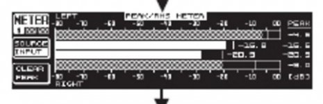
The meter I am referencing on the DEQ is the one in the second attachment.
Set for source = input and hold peak reading.
This reads around -7 dBFS maximum when left on through a movie.(using Toslink)
But it reads - 27 dBFS with a -10 dB test tone from my CD (using homemade RCA to XLR cable).
.
When I get a working (Warranty replacement) DCX I will use the AES/EBU output and input to stay digital until the DCX output, which will be capacitor coupled with no opamps or electrolytics in the signal chain.
Dave
Attachments
OK, one last ask for help.
.
How can I measure the digital output level of my DVD/CD player?
.
Am I using the correct cable to hook the RCA digital output to the AES/EBU balanced input on the DEQ2496?
.
Should I expect the level to be -17dBFS?
And how much resolution do I lose here
Thanks,
Dave
.
How can I measure the digital output level of my DVD/CD player?
.
Am I using the correct cable to hook the RCA digital output to the AES/EBU balanced input on the DEQ2496?
.
Should I expect the level to be -17dBFS?
And how much resolution do I lose here
Thanks,
Dave
Do you mean the SPDIF signal (RF) itself, or the value it represents as a digital signal?
I can post some test signals here if you want to burn them onto CD and look at levels.
FWIW, I have not found the 220R resistor necessary. And RCA connector isn't all that close to 75 ohms, anyway.
I can post some test signals here if you want to burn them onto CD and look at levels.
FWIW, I have not found the 220R resistor necessary. And RCA connector isn't all that close to 75 ohms, anyway.
Dave,
Pano is correct. I don't think the 220 ohm resistor is necessary.
I think you (and the author of your link) is confused on the interfacing requirements for the DEQ. The 220 ohm resistor only "modifies" the loading resistance on the line from 120 ohm to 75 ohm.......but it doesn't change digital (encoded) signal level.
The actual signal level (the level you'd see on an oscilloscope if monitoring) can vary quite a bit and still be recognized as valid by the DEQ2496. But it won't change the displayed signal levels you're seeing on the DEQ meters, since those are representative of encoded signal levels.
Hope that helps.
Dave.
So, if I understand this correctly, the digital signal level is a matter of digital information and the actual voltage of that signal only has to be high enough for the DSP and DAC to receive and decode.
.
I have an "Audio test CD & reference tones, sweep disc" with 50 or so frequencies recorded (supposedly) at either -10 dBFS or 0 dBFS.
.
If I see 17 dB less signal at the DEQ's meters, then the disc represents as it's true level, then either the test disc or more likely the CD player has some digital headroom built in.
.
I think I can give the DEQ up to 15 dB of gain on a specific input, if so then all I need to do is add some gain there if I decide it is even an issue.
.
It does not sound bad at all, so maybe -17 dB does not represent that many bits.
I will have to research this whole issue of level some more.
Thank you all for clarifying the issue for me,
Dave
So where the heck is this transmission line? invisible picture.
.
I have an "Audio test CD & reference tones, sweep disc" with 50 or so frequencies recorded (supposedly) at either -10 dBFS or 0 dBFS.
.
If I see 17 dB less signal at the DEQ's meters, then the disc represents as it's true level, then either the test disc or more likely the CD player has some digital headroom built in.
.
I think I can give the DEQ up to 15 dB of gain on a specific input, if so then all I need to do is add some gain there if I decide it is even an issue.
.
It does not sound bad at all, so maybe -17 dB does not represent that many bits.
I will have to research this whole issue of level some more.
Thank you all for clarifying the issue for me,
Dave
So where the heck is this transmission line? invisible picture.
A 0dBFS signal would have to be DC full scale. Or maybe a square wave with a very asymmetrical duty cycle. A full volume sine wave should have a value of -3dBFS. Sometimes these are refereed to as 0dB, because it is a high as a sine wave can do, digitally.
Davey has explained it well, the volume is coded into the signal, the actual electrical level of the SPDIF signal does not effect the volume level. As long as the DEQ locks onto it, it's valid. I'll post some test signals here tonight and let you know where they register on my DEQ.
Davey has explained it well, the volume is coded into the signal, the actual electrical level of the SPDIF signal does not effect the volume level. As long as the DEQ locks onto it, it's valid. I'll post some test signals here tonight and let you know where they register on my DEQ.
No, a 0dbFS signal doesn't necessarily need to be clipped. An un-clipped sine wave encoded with peaks to the maximum level is 0dbFS. (16bit....-32768 to 32768) "0dbFS" is indicative of peak levels in the waveform and not average level.
Here's a 10 second example. This is not a clipped sine wave but will illuminate the red clipping indicators on your DCX/DEQ if using the digital input. If you modify it in Goldwave (or some other editing program) and reduce its level by 1db, the clipping indicators will no longer illuminate.
Cheers,
Dave.
Attachments
- Status
- This old topic is closed. If you want to reopen this topic, contact a moderator using the "Report Post" button.
- Home
- Source & Line
- Digital Line Level
- Behringer DEQ 2496 input gain