I'm working on some DAC board using old style DAC chip like PCM56, PCM63, PCM1702, PCM1704, AD1862, AD1865, TDA1541 and TDA1543 in NOS mode.
I'm building these boards to be used with Ian's Fifo buffer (http://www.diyaudio.com/forums/digi...ifo-project-ultimate-weapon-fight-jitter.html) and Ian's I2S to PCM daughter board (http://www.diyaudio.com/forums/digi...1541-fifo-universal-i2s-pcm-driver-board.html)
These boards can be configured as single or balanced mode and use a single resistor as IV convertor, preferably an high quality resistor such as Vishay bulk metal foil.
Then I'm planning to implement a Zanden filter (http://www.diyaudio.com/forums/digital-source/8681-zanden-parallel-dac-questions.html) and finally a tubes line stage.
I would like to avoid any capacitor in the signal path, so I'm thinking to work around a totally dc coupled tubes line buffer.
I'm seriously thinking to a Circlotron circuit, since in balanced configuration I can get opposite phase signal to drive directly the Circlotron.
But any other dc coupled tubes design could work as well.
Any suggestion will be appreciated.
Andrea
Last edited:
Sounds nice but you would have to decide on a DAC chip first. I think its too late to do a Zanden stack though, as even the lowly PCM56K is not available in quantities. Only the PCM1702/4 can be bought of the shelf, go with 2 per phase.
Since most all of been done to death anyway maybe (with Ian's I2S-PCM) its time for a deep dive into an NOS PCM1704 board. Its the only one that can take hirez audio.
HD-Tracks to an NOS PCM1704 may be very interesting. I can show you how to set up the PCM1704 to work with passive I/V. Ideally it would be laid out to plug right up to Salas regs.
As far as the tube stage if you really want dc coupled Circlotron output you will need a timer relay in the signal path, don't know if thats any better than a cap, but I'm interested to see what you come up with. Personally I'd stick with the proven WE417 anode follower, or possibly a spot on the board for a nice stepup transformer then a DHT like the 4P1L (most linear tube available), or skip the transformer and two DHT's loftin white.
Lot of possibilities. But I think your best bet is the PCM1704, lot of people listening to 24 bit music nowdays and yours would be one of the first NOS dac's that could play hirez without nasty truncation and no dithering required.
Hi regal,
The second option is a single tube with output transformer like Lundahl LL1674 or LL1930. This could save complexity, probably I could eliminate anti-aliasing filter, since the transformer will cut the upper frequencies.
Andrea
I'm developing all these 8 boards (7 if I cut 1702) to compare them in the same configuration. Consider each board will contain the chip DAC only (2 or 4 for balanced output depending on the chip) and the passive IV (2 to 4 resistors) plus a few other components.Sounds nice but you would have to decide on a DAC chip first. .
Still a few hundreds PCM56P-K in stock from Mouser, Digi-Key, Verical and Arrow. But I think the Zanden filter could be used for all the DAC chip, only for 1704 I need to change the notch center frequency due to 96kHz fs.I think its too late to do a Zanden stack though, as even the lowly PCM56K is not available in quantities. Only the PCM1702/4 can be bought of the shelf, go with 2 per phase.
I usually play 44.1/16 materials only, but I'm very curious to try 1704 in this configuration.Since most all of been done to death anyway maybe (with Ian's I2S-PCM) its time for a deep dive into an NOS PCM1704 board. Its the only one that can take hirez audio.
Your suggestions are wellcome!HD-Tracks to an NOS PCM1704 may be very interesting. I can show you how to set up the PCM1704 to work with passive I/V.
Personally I favor series regulation (I'm just testing my own series regulator and seems to be very quite - http://www.diyaudio.com/forums/power-supplies/212476-well-regulated-power-supply-12.html), anyway these boards do not include power supply, so any option is possible to supply the DACs. I'll provide Kelvin connection for all analog and digital supply.Ideally it would be laid out to plug right up to Salas regs.
I'm not sure I'll need a relay in the signal path, since the Circlotron is naturally balanced. I would like to know how Atmasphere had approached the problem in his preamps, maybe Ralph Karsten could satisfy my curiousity, if he will read this thread.As far as the tube stage if you really want dc coupled Circlotron output you will need a timer relay in the signal path, don't know if thats any better than a cap, but I'm interested to see what you come up with.
My first option is a dc coupled tubes line stage like a Circlotron, I'm thinking to 5687 triode for that.Personally I'd stick with the proven WE417 anode follower, or possibly a spot on the board for a nice stepup transformer then a DHT like the 4P1L (most linear tube available), or skip the transformer and two DHT's loftin white.
The second option is a single tube with output transformer like Lundahl LL1674 or LL1930. This could save complexity, probably I could eliminate anti-aliasing filter, since the transformer will cut the upper frequencies.
Surely the 1704 is one of the chips I'll investigate. I look forward for your hint.Lot of possibilities. But I think your best bet is the PCM1704, lot of people listening to 24 bit music nowdays and yours would be one of the first NOS dac's that could play hirez without nasty truncation and no dithering required.
Andrea
Just got some 5842, some C3m and some 5687.
The idea is a differential pair based on 5842 or C3m in triode mode with a CCS, direct coupled to a 5687 circlotron output stage and direct biased from the differential, that also act as phase shifter to drive 5687 bridge. No transformer, no caps.
DAC filter like Zanden filter, to minimize the phase shift in audio band.
Anyone knows where could I get some custom values air core inductor?
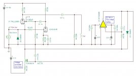
Very low impedance IV tube output stage
This is a variation of the Broskie's IV, using a voltage controlled CCS to null the offset at the input of the DAC.
The DAC see around 1 ohm!
The 1541A DAC could be replaced with any other current output DAC.
This is a variation of the Broskie's IV, using a voltage controlled CCS to null the offset at the input of the DAC.
The DAC see around 1 ohm!
The 1541A DAC could be replaced with any other current output DAC.
Attachments
I have Ian's I2S to PCM daughter board for PCM1704, I use passive I/V 100 ohms 2n2 sound is very good but I need a little more of amplification: I used Partridge 977 MC step up transformers 1:6 but the sound lost all the beautiful lows and magic mids and highs, my idea is to use tubes so I'm here to learn.
Subscribed!
Subscribed!
Which USB to I2S before the I2S to PCM ? Ians board too ?
Think myself about the DYHINK USB with embeded Isolator... But can't understand what is the utlity of the 49.xxx uf.l output socket ? But the others connectors (unluckiliy not uf.l like) out 2.XXX for a 16 bits like the NOS TDA1541 !
MelM : does the Ian's I2S to PCM need to be slaved by an outside masterclock on the USB or the DAC board side ? Or does is just accept I2S inputs and transform it with embeded clock with a lowered jitter ? What is your understanding about the clock uf.l connector on it ?
Sorry Off topic here as Andrea is talking about buffer with tubes... I'm just scratching my head with all those problems of clocks and input stage with multi daughter boards !
Thanks Merlin. Does it accept all Fhz from the USB board or just some particular ones or just a standalone one ? So the UF.L connector of the I2S to PCM board is an input clock uf.l conector...
I find no manual won the thread with the I2S to PCM board... maybe just sended with the device ?!
I find no manual won the thread with the I2S to PCM board... maybe just sended with the device ?!
Let me recommend this balanced tube I/V stage:
http://www.diyaudio.com/forums/digi...s-valve-output-stage-lundahl-transformer.html
http://www.diyaudio.com/forums/digi...s-valve-output-stage-lundahl-transformer.html
Hi Andrea,
A nice place to start again a thread about output tubes stage for the TDA1541...
Did you finish your clock board ?... I went with the Ian's i2S to pcm board. Do you think it needs to be slaved by a Master clock like yours ?
I got the clock PCB last week, now I have to build and test it.
Then I'll start a new thread about crystal oscillator for digital audio, and if anyone was interested I could supply the pcb and the crystal.
Andrea
Hi Andrea,
A nice place to start again a thread about output tubes stage for the TDA1541...
Did you finish your clock board ?... I went with the Ian's i2S to pcm board. Do you think it needs to be slaved by a Master clock like yours ?
Using Ian's FIFO buffer you don't need to reclock the source (USB to I2S), since the FIFO isolates the DAC from the source.
I recommended to use a good master clock close to the DAC (my board's size is 1" x 2") and then send back the clock to the FIFO buffer. To do so without dividers you have to use a master clock at 5.6448 MHz and set Ian's board to 128fs.
FIFO reclock board should be removed.
andrea
Andrea, as you can already see from the responses so far, there are many possible basic solutions and permutations. If you search this site for the terms, 'DAC I/V' I suspect you will get at least one hundred returns.
Philosophically, when utilizing current output DAC chips, I recommend treating the problem like an phono (sans EQ) or microphone amplification application. First, convert current to voltage via a simple relatively low value resistor. Second, amplify the resulting low level signal with the equivalent of a MM phono gain stage without the RIAA EQ network. Typically required signal gain would be in the vicinity of 35dB. Not all DAC chips like this approach. Chips that will work include the R-2R based, AD1865, TDA1541, PCM56, PCM63, PCM1704, and the delta-sigma based PCM179x series.
I do not recommend using high plate voltage tubes without an coupling capacitor or transformer. Too much of a health and equipment safety risk, I think. Either use passive output coupling, or go solid-state. Low plate voltage tubes, however, could be an alternative to explore.
Andrea, as you can already see from the responses so far, there are many possible basic solutions and permutations. If you search this site for the terms, 'DAC I/V' I suspect you will get at least one hundred returns.
Philosophically, when utilizing current output DAC chips, I recommend treating the problem like an phono (sans EQ) or microphone amplification application. First, convert current to voltage via a simple relatively low value resistor. Second, amplify the resulting low level signal with the equivalent of a MM phono gain stage without the RIAA EQ network. Typically required signal gain would be in the vicinity of 35dB. Not all DAC chips like this approach. Chips that will work include the R-2R based, AD1865, TDA1541, PCM56, PCM63, PCM1704, and the delta-sigma based PCM179x series.
Hi Ken,
In the 90s some people used to have an unity gain for i/v then amplifing... steel valid ?
Hi Ken,
In the 90s some people used to have an unity gain for i/v then amplifing... steel valid ?
Hi, Eldam,
I'm uncertain of what topology you refer to by, "unity gain for I/V". Could you describe this circuit in a bit more detail?
how to connect the clocks of all these boards
thanks Andrea and Merlin,
I want just use the I2S to pcm. Ian Fifo is too much expensive for my money and in my mind for diy, with all the solutions (isolator, crystal, it is coster than a brand new IDSD NANO from IFI developed by T. Loesch e.g.! Id on't know if it can be sourced at a lower cost or not but for me it's a no go... I just go for the the PCL board for silmutanous board as it seems an essential step for SQ §... I have an AYA2 on the fire for cooking as well... so a lot of project and not ears enough !
Well my understanding is low here !
1) : The I2S to PCM need an external clock but the one (bclk) in the I2S signal ? response from Merlin is Yes !
2) If possible I plan for the less costly : Isolated XMOS DSD DXD 384kHz high-quality USB to I2S/DSD PCB with ultralow noise regulator - DIYINHK : you can choose the I2S output Fhz by wirering and there is a 51.XXX outpout clock with UF.L
3) with this USB to I2S with isolator (USB XMOS is isolated like FIFO) and I2S xout with uf.l connector at 51.xxx : Do I slave from it the I2S to PCM : in another word : does the I2S to PCM reclock this input Fhz depending to a lower one equal to the data format of the song or there is no link between the both ?
4) Or can I do in a better way slave the Ian I2S to PCM with a compatible Fhz for the NOS TDA1541 (so : 5.xxx).
In one word I don't understand which dictate the speed in the chain and how is played the songs recorded with more than the Red book like 20/96 khz or more ??? My understanding is you force the format output with wirering and the I2S to PCM do not change it but need a higher frequency clock to be jitter stable! Correct ?
@ Andrea : Good news for your kit, I hope you will have a significant result. this site sell genuine NSD crystal at 12.xxx sourced directly from japan... (if you want to make a try in the perspective to give an other less expensive choice for your Kit (if Laptech is expensive e.g.).
As it's not the right place, I will re ask if no simple answer in the ad hoc thread.
Thanks
Using Ian's FIFO buffer you don't need to reclock the source (USB to I2S), since the FIFO isolates the DAC from the source.
I recommended to use a good master clock close to the DAC (my board's size is 1" x 2") and then send back the clock to the FIFO buffer. To do so without dividers you have to use a master clock at 5.6448 MHz and set Ian's board to 128fs.
FIFO reclock board should be removed.
andrea
thanks Andrea and Merlin,
I want just use the I2S to pcm. Ian Fifo is too much expensive for my money and in my mind for diy, with all the solutions (isolator, crystal, it is coster than a brand new IDSD NANO from IFI developed by T. Loesch e.g.! Id on't know if it can be sourced at a lower cost or not but for me it's a no go... I just go for the the PCL board for silmutanous board as it seems an essential step for SQ §... I have an AYA2 on the fire for cooking as well... so a lot of project and not ears enough !
Well my understanding is low here !
1) : The I2S to PCM need an external clock but the one (bclk) in the I2S signal ? response from Merlin is Yes !
2) If possible I plan for the less costly : Isolated XMOS DSD DXD 384kHz high-quality USB to I2S/DSD PCB with ultralow noise regulator - DIYINHK : you can choose the I2S output Fhz by wirering and there is a 51.XXX outpout clock with UF.L
3) with this USB to I2S with isolator (USB XMOS is isolated like FIFO) and I2S xout with uf.l connector at 51.xxx : Do I slave from it the I2S to PCM : in another word : does the I2S to PCM reclock this input Fhz depending to a lower one equal to the data format of the song or there is no link between the both ?
4) Or can I do in a better way slave the Ian I2S to PCM with a compatible Fhz for the NOS TDA1541 (so : 5.xxx).
In one word I don't understand which dictate the speed in the chain and how is played the songs recorded with more than the Red book like 20/96 khz or more ??? My understanding is you force the format output with wirering and the I2S to PCM do not change it but need a higher frequency clock to be jitter stable! Correct ?
@ Andrea : Good news for your kit, I hope you will have a significant result. this site sell genuine NSD crystal at 12.xxx sourced directly from japan... (if you want to make a try in the perspective to give an other less expensive choice for your Kit (if Laptech is expensive e.g.).
As it's not the right place, I will re ask if no simple answer in the ad hoc thread.
Thanks
- Status
- This old topic is closed. If you want to reopen this topic, contact a moderator using the "Report Post" button.
- Home
- Source & Line
- Digital Line Level
- DAC IV and buffer, need your contribution