Hi Mike,
Yes the level conversion is also achieved by using the isolated I2C outbreak. You have to connect per the manual.
The I2C pins of the DAC are supposed to be 5V tolerant, but to be on the safe side it is best to use a level converter. For that reason I updated the manual.
I don't know if you are using one or more of the controller's pin's to switch sources without any form of isolation? If so, then the controller and DAC/modules need to have a common ground.
Hi Corpius, sorry for re-opening this topic, as I don't know if this is the correct channel to use for CE644 support...
I have a Buffalo III (stereo) and the inputs are from a 4 spdif level converter (no mux), and a sidecar.
I also have the CE644 v1.2. Is it possible to address the inputs (3 to 6) without the 2 adress lines used by the Mux in the manual?
Thanks and regards,
I have a Buffalo III (stereo) and the inputs are from a 4 spdif level converter (no mux), and a sidecar.
I also have the CE644 v1.2. Is it possible to address the inputs (3 to 6) without the 2 adress lines used by the Mux in the manual?
Thanks and regards,
Hi Adrianos,
Yes, you can address all spdif inputs (1 to 8).
The easiest way to address inputs 3-6, without having to re-write large parts of the code, is to replace the next function:
into this function:
The only difference is this line
Input 1 becomes input 3, input 2 becomes input 4 and so on.
I'm not sure how you want to connect the spdif channels using the sidecar, because the sidecar connects the four spdif channels comming from the spdif level converter to inputs 1 to 4.
Yes, you can address all spdif inputs (1 to 8).
The easiest way to address inputs 3-6, without having to re-write large parts of the code, is to replace the next function:
Code:
void setInputChannel(byte value){
	//This register set the input channel to get the desired input. Note: This code is dedicated to my own Buffalo 3
	switch (value){
	  case 1:	// SPDIF1
			writeSabreReg(0x12,0x01);        // Reg 18: Set SPDIF to input #1
			break;
	  case 2:	// SPDIF2
			writeSabreReg(0x12,0x02);        // Reg 18: Set SPDIF to input #2
			break;
	  case 3:	// SPDIF3
			writeSabreReg(0x12,0x04);        // Reg 18: Set SPDIF to input #3
			break;
	  case 4:	// SPDIF4
			writeSabreReg(0x12,0x08);        // Reg 18: Set SPDIF to input #4
			break;
	  case 5:	// SPDIF5
			writeSabreReg(0x12,0x10);        // Reg 18: Set SPDIF to input #5
			break;
	  case 6:	// SPDIF6
			writeSabreReg(0x12,0x20);        // Reg 18: Set SPDIF to input #6
			break;
	  case 7:	// SPDIF7
			writeSabreReg(0x12,0x40);        // Reg 18: Set SPDIF to input #7
			break;
	  case 8:	// SPDIF8
			writeSabreReg(0x12,0x80);        // Reg 18: Set SPDIF to input #8
			break;
	}
}
into this function:
Code:
void setInputChannel(byte value){
	//This register set the input channel to get the desired input. Note: This code is dedicated to my own Buffalo 3
	value += 2;
	switch (value){
	  case 1:	// SPDIF1
			writeSabreReg(0x12,0x01);        // Reg 18: Set SPDIF to input #1
			break;
	  case 2:	// SPDIF2
			writeSabreReg(0x12,0x02);        // Reg 18: Set SPDIF to input #2
			break;
	  case 3:	// SPDIF3
			writeSabreReg(0x12,0x04);        // Reg 18: Set SPDIF to input #3
			break;
	  case 4:	// SPDIF4
			writeSabreReg(0x12,0x08);        // Reg 18: Set SPDIF to input #4
			break;
	  case 5:	// SPDIF5
			writeSabreReg(0x12,0x10);        // Reg 18: Set SPDIF to input #5
			break;
	  case 6:	// SPDIF6
			writeSabreReg(0x12,0x20);        // Reg 18: Set SPDIF to input #6
			break;
	  case 7:	// SPDIF7
			writeSabreReg(0x12,0x40);        // Reg 18: Set SPDIF to input #7
			break;
	  case 8:	// SPDIF8
			writeSabreReg(0x12,0x80);        // Reg 18: Set SPDIF to input #8
			break;
	}
}
The only difference is this line
Code:
value += 2;I'm not sure how you want to connect the spdif channels using the sidecar, because the sidecar connects the four spdif channels comming from the spdif level converter to inputs 1 to 4.
Thanks for your answer!!!
Let me try to explain a bit more...
Actually I have the BIII (stereo mode) and intend to use the followuing inputs (no matter the sequence):
1- DSD (from amanero)
2- I2S (from teleporter)
3- Spdif 1 (RCA)
4- Spdif 2 (RCA)
5- Spdif 3 (BNC)
6- Spdif 5 (AES) maybe TOS adapter.
I have a sidecar, an OTTO II anda a 4channel SPDIF adapter (not a mux).
By the manual, I figured out how to connect the CE644 to control the sidecar (switch pcm/DSD x SPDIF), the OTTO (to switch between DSD/PCM and Teleporter inputs).
But the manual mentions 2 address lines (D23 and D24) to control the 4:1 MUX... As I'm not using this board, only the 4 ch level converter, I believe the spdif input switch should be done by FW, programing Sabre's register 18 (thanks for your site explanation, I'm really a newbie on this...).
So, the main doubt is:
- May I dont use the 4:1MUX (use the converter only) without any change to the FW?
- Once not using the 4:1MUX, may I leave the 2 address lines (D23/D24) open (not connect to anywhere)?
I also may give a try on the weekend, as I have all the stuff but if we can get this point clear I could increase the chances to a "happy end"!")
Thanks again for your support!
Let me try to explain a bit more...
Actually I have the BIII (stereo mode) and intend to use the followuing inputs (no matter the sequence):
1- DSD (from amanero)
2- I2S (from teleporter)
3- Spdif 1 (RCA)
4- Spdif 2 (RCA)
5- Spdif 3 (BNC)
6- Spdif 5 (AES) maybe TOS adapter.
I have a sidecar, an OTTO II anda a 4channel SPDIF adapter (not a mux).
By the manual, I figured out how to connect the CE644 to control the sidecar (switch pcm/DSD x SPDIF), the OTTO (to switch between DSD/PCM and Teleporter inputs).
But the manual mentions 2 address lines (D23 and D24) to control the 4:1 MUX... As I'm not using this board, only the 4 ch level converter, I believe the spdif input switch should be done by FW, programing Sabre's register 18 (thanks for your site explanation, I'm really a newbie on this...).
So, the main doubt is:
- May I dont use the 4:1MUX (use the converter only) without any change to the FW?
- Once not using the 4:1MUX, may I leave the 2 address lines (D23/D24) open (not connect to anywhere)?
I also may give a try on the weekend, as I have all the stuff but if we can get this point clear I could increase the chances to a "happy end"!
Thanks again for your support!
Last edited:
I think that I understand you now. No need to re-write the code .
The spdif input switching is done by the firmware (register 18) indeed. You don't need to use the 4:1 mux, just connect the 4 channel spdif converter board to the sidecar and connect pin D21 (controller) to the sidecar input "B". The controller will take care of switching the sidecar when you select one of the four spdif inputs. It will also take care of register 18 by making sure that the correct spdif input is being selected at te DAC chip.
You can set the inputs as desired at the "input settings menu" by setting the input format (INF), as explained on page 10 of the manual. You'll need to do this for each of your six inputs.
You can leave D23 and D24 floating. They're only needed when using the 4:1 mux instead of the 4-ch spdif level converter board. Besides, the 4:1 mux ouputs I2S, not spdif.
.The spdif input switching is done by the firmware (register 18) indeed. You don't need to use the 4:1 mux, just connect the 4 channel spdif converter board to the sidecar and connect pin D21 (controller) to the sidecar input "B". The controller will take care of switching the sidecar when you select one of the four spdif inputs. It will also take care of register 18 by making sure that the correct spdif input is being selected at te DAC chip.
You can set the inputs as desired at the "input settings menu" by setting the input format (INF), as explained on page 10 of the manual. You'll need to do this for each of your six inputs.
You can leave D23 and D24 floating. They're only needed when using the 4:1 mux instead of the 4-ch spdif level converter board. Besides, the 4:1 mux ouputs I2S, not spdif.
Last edited:
CE644/CE328
Hi,
i have CE 644 and Ce 328 boards from you. but with both the LCD display is way to dark. now i have seen on the LCD extra i0 from electro fun there is a resitor (R2) on the backlight line. can i remove R2 as there is still the mcp42010 on the shield which give me a max of 4.9 V and the resistor brings this down to 2.8 V.
thx
branko
Last edited:
Yes, the OLED. I had the PCB's made at oshpark.com. They have a 3 board minimum order. I populated 2 boards. Probably won't use the third one if you're interested.
I'm interested! Please PM me with payment details.
Hi schultzsch,
I am no expert but I did manage to build one and have it working now. What do you need help with?
Hello pixelpusher,
I need first to write a bootloader, I think...
Can this be done with the arduino app?
After I write the bootloader what files from Corpius site to I have to write and in which order? What program to use to write these files on the mcu?
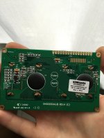
My oled display is version A, not sure but I wll attach a photo
I want to use an apple remote and bourns pec11r rotary encoder.
For the connection of the rotary encoder I am a little bit confused.
It has 5 pins : A C B and 1 2.
A from encoder goes to channel A from controller
B from encoder goes to channel B from controller
C from encoder goes to common/gnd from controller
1 from encoder goes to switch/button 5 from controller
2 from encoder goes to common/gnd from controller
I have also some boards to sell(maybe 7) so please feel free to ask.
Attachments
Last edited:
If your chip does not have a boot loader you will need to "Burn" one using the ISP header. The USB/serial connector will not work without a boot loader present. The CE-Designs website has instructions and links to the files needed to do this. After you have the boot loader installed you can upload the firmware using the Arduino IDE.
I had to make a few adjustments to the firmware code to get it working. I am a programming novice so it has been quite the learning experience. The code is described as unfinished but seems to work for my needs. I am continuing to study the programming so I may be able to add some more controls in the future.
I can't comment on the encoder as I've not hooked it up yet. I did use one with the v1.2 controller. In the next few days I will try to get that working.
I managed to burn the boot loader with arduino mega using some tutorials found on the net
Having Rev A OLED I had removed characterOLED library but when I try to compile the code it gives some errors
I do not have any ideas how to solve this.
Can you please share your working version?
My laptop doesn`t want to recognize the ftdi chip, maybe because is runnin win 7 64bit?
Or is there something else that I do wrong?
Thanks.
I compiled with arduino 1.0.1 and arduino 1.6.6
In arduino 101 fails to compile, in 166 it compiles but I can not find atmega644 in boards list, even if I copy atmega644 libraries in arduino hardware folder.
I will attach two text files from the two versions of arduino.
In arduino 101 fails to compile, in 166 it compiles but I can not find atmega644 in boards list, even if I copy atmega644 libraries in arduino hardware folder.
I will attach two text files from the two versions of arduino.
Attachments
Those errors all seem to relate to multiple definitions. I suspect that it is trying to load too many libraries.
I am certainly no expert on programming these things. Here's what I did. I used Arduino IDE 1.01. All of the files from Github must be in a folder within the sketch folder. The libraries then will show up as tabs in the IDE. I did not install any libraries in the Arduino IDE program. I am using the Rev C OLED. I had to uncomment the line; #define CHARACTER_OLED in the file SabreController.h and comment out the line; #include “OLEDFourBit.h" in the file SabreCE.ino
One line was missing a ; on the end which threw a compiling error. I don't remember where this was but it should be easy to find once you remove all those errors for multiple definitions.
When I was finally able to upload the files the controller worked good but did not display the correct sample rate. Robert helped me out by sending me his working files. I was able to find the discrepancy by comparing his files to mine. I changed the line "controller.sabreDAC.getSampleRate();” in the .ino file to "controller.sabreDAC.setSampleRate();” and the correct sample rate displayed for PCM files. There is still an issue with the sample rate display for DSD files. I have a few ideas on a solution but have not yet tried to correct this.
Hope this helps!
- Status
- This old topic is closed. If you want to reopen this topic, contact a moderator using the "Report Post" button.
- Home
- Source & Line
- Digital Line Level
- ES9018 I2C controller