Heart of the system
I also think Chapark has done a great job and offers great value for money, I too will probobly buy a board, but I can see where Dahlberg and others are comming from...The search for the absolute best of the best...
To me the source, speakers and amplifiers are all simpler than the DSP/ crossover / Eq / DAC's, and in particular the area of oscillator & clock(s) implementation is of particular concern as I dont fully understand all the various options. There are many ways to link them up and get sound, but which is the best...?
Maybe one or two of the top digital dudes on this forum can suggest the best way to do this, a basic block layout with a signal flow and clock control. Then all potential group buyers can wish list features and specs, discuss and arrive at some sort of conclusion which we agree on.
If its of any interest I can get fully populated PCB's built and tested to military spec in batches of 100 for a very competative rates.
Cheers
Derek.
More gold and copper a better calculator do not make.
digital DSP = digital digital signal processing
The jitter war was fought and effectively won.
The single weakest link in audio remains transducers. HD and IMD are at several magnitudes of order above that of virtually all commercially produces DACs for consumer and pro markets.
The next weakest link is tendency for programmers making DSP emulate analog filters, rather than exploring the possibilities, or letting user load filters. The DCX2496 could be easily patched to do this.
Chapark is attempting to do this, and appears to have the chops for it.
MiniDSP has got it, but limited to about 6k tap filter. For filters capable of dealing with rooms with long decay times 16k-32k taps are needed.
The more the merrier. It spreads the knowledge, and lowers the price.
I'll check back in thirty pages.
Regards,
Andrew
I also think Chapark has done a great job and offers great value for money, I too will probobly buy a board, but I can see where Dahlberg and others are comming from...The search for the absolute best of the best...
To me the source, speakers and amplifiers are all simpler than the DSP/ crossover / Eq / DAC's, and in particular the area of oscillator & clock(s) implementation is of particular concern as I dont fully understand all the various options. There are many ways to link them up and get sound, but which is the best...?
Maybe one or two of the top digital dudes on this forum can suggest the best way to do this, a basic block layout with a signal flow and clock control. Then all potential group buyers can wish list features and specs, discuss and arrive at some sort of conclusion which we agree on.
If its of any interest I can get fully populated PCB's built and tested to military spec in batches of 100 for a very competative rates.
Cheers
Derek.
Thanks
")
That's the whole idea.The search for the absolute best of the best...
The jitter war was fought and effectively won.
.....
How, do You mean, was this done?
/
Last edited:
I offer the picture below as a reference for the discussion and would claim that there is only one source for error if we stay in the digital domain and that is information loss or alteration. NB it is a logical scheme so the functions need to be allocated to a physical reality. Anyways, to get a clock as jitter free as possible at "ci" is the goal. An other is not to have "slip" i.e. information loss due to the combination of asynchronous communication and absence of storage to cater for the timing difference in the clock domains. In practice, a clock feedback CF is necessary in order prevent slip at the same time keeping the clock distribution lines (C3->ci) as short as possible. This is still a synchronous mode of operandum it's just that the feeding direction is reversed - this was made by Linn long time ago with an extra set of cable between the DAC and the Drive.
I would think that any "Calculation" box could be time wise isolated from the D/A process leaving only aspects of calculation precision to be considered i.e. who writes the best (most audible transparent) code for signal manipulation.
To be remembered is that when a level for time t is defined in output stage of an D/A, the level can either be defined by the digital word fed into the D/A (i.e. an ideal clock was at hand) or a combination of the clock and eventual calculation of the digital representation of the signal level. I mean, signal manipulation can be heard, hence its name. And no, the passband is not "unaltered" in the digital domain calculation wise.
On the DSP as a circuit, only calculation capacity is of interest - nothing else.
Attachments

Last edited:
How, do You mean, was this done?
/
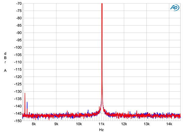
Fig.11 Musical Fidelity V-DAC II, high-resolution jitter spectrum of analog output signal, 11.025kHz at –6dBFS, sampled at 44.1kHz with LSB toggled at 229Hz: 24-bit USB data (left channel blue, right red). Center frequency of trace, 11.025kHz; frequency range, ±3.5kHz.
From: Sterophile
Reinventing the rounder wheel. Somebody's got to do it. When I see such information, it is apparent that 24bit noise floor is turning into mighty flat playing field. Many resistors are noisier.
Let me know if you find an audio transducer with THD <-70dB.
Anyway this topic is about high bandwidth calculators, not DAC/ADC.
Andrew
What specifically are you looking for? The design continuum's already been discussed on this thread along with the desirability of an interconnect standard. Also discussed are existing components which can be leveraged to implement various options and some of the tradeoffs between them. The discussion around performance requirements is a bit more hand waving---see the bits about DIY budgets and the cost of measurement gear---but it's there too.Maybe one or two of the top digital dudes on this forum can suggest the best way to do this, a basic block layout with a signal flow and clock control.
Well, if it's nonsense it's 20dB above the ambient noise floor and 10-15dB above the driver distortion floor. Curious definition of nonsense if you ask me; perhaps a revisit of numerical precision and scaling is in order.This is nonsense.
People,
I stumbled across this thread - and have only read bits and pieces, so I apologise if the discussion has speared off into a different direction.
The aim of my crossover was to allow a fairly arbitrary ADC and DAC to be integrated to the Analog Devices ADAU1442.
I chose to use CS4398 DACs and CS5361/81 ADCs - though the interface is really LRCK, MCK, BCL, some control and lots of power and ground.
I am happy to provide:
- The CAD files
- The software for the controller
- The DSP code
- Practical assistance in using this, and if you are really hardcore the bare DSP and ADC/DAC boards from PCBCART will be really cheap as they have all the photoplots (couldnt say how much but I would hazard a guess of in the region of 10-20A$ or US$)
For those concerned abut clocks, this does use a simple crystal oscillator. You could swap that out for pretty much anything. THere are a plethora of options with the ADAU chips, including:
- Using the ASRC (which I do)
- External master clock - simple config of the ADAU (hmm simple...)
- Use the ADAU as master
I originally did this as someone asked if my old DSP XO could use a "decent CODEC". OK the old one was on paper adequate but not earth shattering - and I kind of liked the idea of being able to mix and match digitisers and DACS.
If you want to play with this let me know
- Schematics and PCBs are in ALTIUM, though could be translated to most packages
- The interfaces are super obvious - draw a line between a DSP and DAC and you get the idea of the signals
- There is some surface mount, but not so much that an experienced DIYer should be that scared. I made mine in a toaster oven and had a 6 of 6 success rate on the DSPs, and 20 of 20 on AD/DA boards.
Phil
Well, if it's nonsense it's 20dB above the ambient noise floor and 10-15dB above the driver distortion floor. Curious definition of nonsense if you ask me; perhaps a revisit of numerical precision and scaling is in order.
As pertains to #74, elements other than the DAC are responsible for your observations.
Why do you insert a power amplifier, speaker, microphone, microphone preamplifier into signal path with DAC as device under test?
Power amplifier completely buffers speaker from DAC.
What are signals at input to the two different power amplifiers? How do these signals measure? Virtually identical? What is the test stimulus? Swept sine, stepped sine, multiple sine, periodic noise?
In relation, how does output of power amplifiers measure with resistive load v load of driver? What is influence of speaker back EMF at amplifier outputs? What is output impedance of each power amplifier? How does driver signal at terminals correlate to acoustic response?
I read your posts; your electronic knowledge and skills are sound, but your measurement practice in this instance tells nothing useful about the performance of the DAC.
This is not nonsense, I apologize for using the word in my previous post in lieu of greater details inquiring of your methods and reasoning with respect to measurement practices.
Regards,
Andrew
Do you happen to know if a SigmaDSP biquad operating in double precision is 28 bit coefficients and feedback with a 56 bit accumulator, or 56 bit coefficients, feedback, and accumulate? The datasheet's ambiguous and I don't recall seeing anything that spelled it out in the SigmaStudio docs or over at the Analog EZ forums.ADAU1442
End to end system measurements seem the best way of verifying one is correctly composing individual components' characteristics when desiging to some overall performance target. Strangely, they're not often done in audio, so the result is often performance limits on the integration between components rather than the components themselves. I mentioned that particular case in this thread as I was looking at the interaction of digital volume control with power amplifier gain. The measurements are swept sine in HOLMImpulse with the DSP XO+EQ operating on 16 bit samples with double precision floating point internally and the DAC output going direct to the power amps.Why do you insert a power amplifier, speaker, microphone, microphone preamplifier into signal path with DAC as device under test?
That's more or less the standard/default/mainline configuration one gets with a PC crossover so it serves as a good example of how analog and digital components have to be designed to work together.
The majority of audio data is in redbook format (or non-uprezzed compressed versions thereof) and the majority of DSP implementations do not increase the bits per sample on the fly---the primary exception I'm aware of is the recently discontinued Squeezebox line, though there are probably others. If the source is local and storage is unconstrained it's trivial enough to change up to 24 bit and avoid the problem that way. But that's often not an option when streaming internet radio or such. In a DIY DSP it's often trivial to output 24 (or 32) bit samples regardless of the input sample size in forward time processing (reverse time processing is more involved but not commonly used).
Upping the bit depth from 16 to 24 unlocks someplace between 0 and 5 additional bits of resolution depending on the DAC's analog performance and may or may yield benefit from the increased number of guard bits (depends on the filtering and gain structure and how they're implemented) but that wasn't what I happened to want to measure in that particular case. Few DACs have more than 19 bit resolution and even fewer implement 19 bit linearity so the sample size increase has a way of yielding somewhere around 15dB of improvement (depending on the DAC used and part to part variations in fab). So it's actually kind of hard to throw digital bits at the problem of excess power amp gain.
Upping the bit depth from 16 to 24 unlocks someplace between 0 and 5 additional bits of resolution depending on the DAC's analog performance and may or may yield benefit from the increased number of guard bits (depends on the filtering and gain structure and how they're implemented) but that wasn't what I happened to want to measure in that particular case. Few DACs have more than 19 bit resolution and even fewer implement 19 bit linearity so the sample size increase has a way of yielding somewhere around 15dB of improvement (depending on the DAC used and part to part variations in fab). So it's actually kind of hard to throw digital bits at the problem of excess power amp gain.
Question: "Do you happen to know if a SigmaDSP biquad operating in double precision is 28 bit coefficients and feedback with a 56 bit accumulator, or 56 bit coefficients, feedback, and accumulate? The datasheet's ambiguous and I don't recall seeing anything that spelled it out in the SigmaStudio docs or over at the Analog EZ forums."
Yhea - the datasheets are enough to use the devices, but leave a fair bit of the internals either minimally explained or not at all. That said, I have found Analog Devices to be pretty helpful with queries.
You configure the SigmaDSP as either single or double precision in their "programming tool".
- Single precision is 28 bits - which all arithemitic operations within the biquads are done in 28 bit precision. I do not use this.
- Double precision uses 28 but data and coefficients and all arithmetic within the biquad calculations is done in 56 bit and truncated at the end of the calcs.
The 28 bit part is implemented to allow filters gain, so 24 bit input coefficients are represented as 0X0.xxxxxx (i.e. zero plus 24 bits).
If you put in 16 bit data the last 8 bits are zero - at least until you run the data through a filter!
While the idea of all data being in 56bit format might seem "better" the math of it points out the futility. 24 bit is 140 odd dB DNR... With this "double" bit depth I have not been able to see artefacts or results of coefficients in filters messing me around - though I have not gone to the extent of digidal domain analysis of the data.
Qusp: Not sure who it was that prompted me to this anymore - I do recall lending them my old AD1940 DSP development board through....
If you're targeting SigmaDSP parts SigmaStudio generates the necessary code. It's a free download. If you're targeting Cortex M4 look at ARM's CMSIS DSP library and examples. More generally, there are several open source implementations of the Bristow-Johnson cookbook.Is there any open source code for a dsp xo that would be useful if you actually already had the hardware?
Yah, though I don't feel it's fair to take up Brett's time if I'm not planning to use the part. I've found low frequency biquads can require 16 or more guard bits in coefficients and feedback to maintain accurate Q0.23 output with the usual [ -0.25, 0.25 ) scaling---more here---so a 28 bit filter path with 56 bit accumulation is maybe not so attractive depending on the number of accurate bits one requires.That said, I have found Analog Devices to be pretty helpful with queries.
I'm in the same boat..
was looking around and the most simple and "elegant" solution without having to code a ton of stuff was from AD. I've ordered up some samples and hopefully will have some free time to work up at least a rough schematics by mid week.
I'm going with ADAU1445 and ADAU1966
This Combo will open the door to a 16ch system, not that you will ever need to use all of them, but why not start with a solid stepping stone rather then with loose gravel.
it will be controlled with HiFiDuino through an Arduino Due. Will be using SPI as main protocol rather than I2C due to its speed.
Anyways...
I will most likely start a thread once i get the parts and have a schematic in hand
Adrculda,
if you want a kick start on this I am happy to help. If you look at my blog I have put all the CAD files and source code for the ADAU1442.
Happy to assist with schematic reviews and will happily try to asist with some of the oddities that I am sure you will bump into on the implementation for these chips.
That said, once running they have proven to be bullet proof and very stable.
You wont find that I2C / SPI speed is such a big deal - there is not a lot of code to be loaded, and unless you are planning to do some really funky things with real time changes to coefficients, the amount of data you send to configure filters etc is pretty minor. If you have either an I2C or SPI bus logger, then go for that protocol!
Have fun!
By the way...
Just this weekend gone I connect my ADAU1442 DSP to my computer using the optical interface (in and out).
The optical output from the computer into the DSP worked just fine, but buggered if I could get the audio from the DSP into the computer.
The weird thing was that I could hook two of the ADAU1442 DSP's together (optical out to optical input) and things worked just fine - but nogo in sending data to the PC!
After several hours of self doubt and head scratching I finally dug into the DSP configuration code, then into the datacheet, which led to an errata from Analog Devices which I would paraphrase as:
"Ooops. Some pillock has set the SPDIF 'V' bit high on ADAU1442 serial data out, and done it in hardware. Every sane piece of audio hardware will ignore any data we send out. Our bad, Sorry."
Which translates to the SPDIF data output from this IC having the Data Valid bit set to "INVALID" meaning that most devices ognore the data and go into mute. Bugger.
Ardculda - just check this with the ADAU1445...
Qusp: Not sure who it was that prompted me to this anymore - I do recall lending them my old AD1940 DSP development board through....
not me then, no I just remember sending you a PM maybe a year ago asking if the design could be bent to some ESS dacs.
but no I havent absconded with your eval board =)
- Status
- This old topic is closed. If you want to reopen this topic, contact a moderator using the "Report Post" button.
- Home
- Source & Line
- Digital Line Level
- High end all digital dsp crossover ?