Total 134
Gogi x1
Hi Gogi,
The fist PCM GB was closed. So this interesting list is no longer working. I'v put your name on the new waiting list, which is here:
http://www.diyaudio.com/forums/grou...-pdif-fifo-kit-group-buy-152.html#post3729983
Have a good weekend.
Ian
From you waveforms, CLK signal looks good, but LLLR and DL, DR are definitely too low(compare with CLK), did you measure them with same probe?
Try to measure those PCM signals again with/without load (TDA1541A) to see it that is a load related problem. Probe set at X10.
Good luck
Ian
Hi Ian,
I installed the fifo, isolator, and dual clock along with the PCM board and now 192kHz material plays successfully. I did not change the signal attenuation at all.
Happily listening to music right now. It sounds very good, and that's with the clocks that came with the board.
Thanks for your help.
Ben
Good to know that. You can challenge the 384KHz the next
 .
.I suspect the reason was the ground loop. The isolator cuts ground loop from all digital front end which may introduce EMC noise into DAC.
Enjoy!
Ian
Last edited:
Distorted Sound - BCLK Problem?
Hi Ian,
I've installed the I2S to PCM board directly above the single XO PCB.
Also installed all UF.L connectors and using coax cables into the I@S to PCM board, and out to DAC board. All connectors have been correctly soldered and checked for shorts and connectivity.
Jumpered according to manual for offset binary (JOB)
For testing, using a 1KHz PCM/wave file from PC to DAC. I've checked BCLK going into the I2S to PCM, and it's clean/steady signal.
The sound is very distorted from the right channel, and very noisy (distortion bursts) on left channel.
At DAC input, I see that the BCLK is stopping and starting - as per the manual.
I've tried 2 different TDA1541A devices, with the same result on both.
I'm using a 50 ohm I to V resistor. What should be a sine wave on the output is extremely distorted.
My new PCB is identical to previous PCB, except for separate DL / DR inputs.
Pin 26 connected to -5V
Any suggestions as to what the issue might be?
Added: All signals into DAC are 3.5V
Last edited:
Hi Ian,
I've installed the I2S to PCM board directly above the single XO PCB.
Also installed all UF.L connectors and using coax cables into the I@S to PCM board, and out to DAC board. All connectors have been correctly soldered and checked for shorts and connectivity.
Jumpered according to manual for offset binary (JOB)
For testing, using a 1KHz PCM/wave file from PC to DAC. I've checked BCLK going into the I2S to PCM, and it's clean/steady signal.
The sound is very distorted from the right channel, and very noisy (distortion bursts) on left channel.
At DAC input, I see that the BCLK is stopping and starting - as per the manual.
I've tried 2 different TDA1541A devices, with the same result on both.
I'm using a 50 ohm I to V resistor. What should be a sine wave on the output is extremely distorted.
My new PCB is identical to previous PCB, except for separate DL / DR inputs.
Pin 26 connected to -5V
Any suggestions as to what the issue might be?
Added: All signals into DAC are 3.5V
Did you confirm your 1541A DAC works good with I2S input? If it works with I2S, then swith it to PCM mode and bridge to I2S by the PCM board.
If it is possible, post some picture.
Hope you can fix it soon.
Ian
Hi Ian and others,
I'm struggling too..
1541A running I2S
1. separate Pin 27 from 28 (+5V)
2. tie pin 27 to 26 (-5V)
3. separate pin 2 from 4 (BCK/DR)
4. feed LLR to pin 1
5. feed CLK to Pin 2
6. feed DL to pin 3
7. feed DR to pin 4
Theres a crossover on the ribbon cable in that yellow goes to pin one and red to pin two.
I checked it thirty two times but must have missed something - and in the process now can't get I2S lock on the i2S board.
Replaced every cable and even 1541A. All voltages measure correctly at the DAC, FIFO has lock. Guess I fried the PCM board with all the power up/down etc - no I2S lock anymore. Should have been so simple grr.
I'll try back with I2S tomorrow have single XO board and can remove the isolator if I need to in order to confirm that I've fried the PCM.
Can someone just have a quick look at the steps I took above?.. I double checked with data sheet, continuity meter, I was really sure it would work.
The other thing I noticed was that when I did get I2S lock at the PCM it was regardless of whether the PC was connected or not. I could restart the PC, leave the rest on, and the I2S lock would stay light. Should the I2S lock only come on when signal present?.
Thanks,
Shane
I'm struggling too..
1541A running I2S
1. separate Pin 27 from 28 (+5V)
2. tie pin 27 to 26 (-5V)
3. separate pin 2 from 4 (BCK/DR)
4. feed LLR to pin 1
5. feed CLK to Pin 2
6. feed DL to pin 3
7. feed DR to pin 4
Theres a crossover on the ribbon cable in that yellow goes to pin one and red to pin two.
I checked it thirty two times but must have missed something - and in the process now can't get I2S lock on the i2S board.
Replaced every cable and even 1541A. All voltages measure correctly at the DAC, FIFO has lock. Guess I fried the PCM board with all the power up/down etc - no I2S lock anymore. Should have been so simple
grr. I'll try back with I2S tomorrow have single XO board and can remove the isolator if I need to in order to confirm that I've fried the PCM.
Can someone just have a quick look at the steps I took above?.. I double checked with data sheet, continuity meter, I was really sure it would work.
The other thing I noticed was that when I did get I2S lock at the PCM it was regardless of whether the PC was connected or not. I could restart the PC, leave the rest on, and the I2S lock would stay light. Should the I2S lock only come on when signal present?.
Thanks,
Shane
Last edited:
Hi Ian and others,
I'm struggling too..
1541A running I2S
1. separate Pin 27 from 28 (+5V)
2. tie pin 27 to 26 (-5V)
3. separate pin 2 from 4 (BCK/DR)
4. feed LLR to pin 1
5. feed CLK to Pin 2
6. feed DL to pin 3
7. feed DR to pin 4
Theres a crossover on the ribbon cable in that yellow goes to pin one and red to pin two.
Can someone just have a quick look at the steps I took above?.. I double checked with data sheet, continuity meter, I was really sure it would work.
The other thing I noticed was that when I did get I2S lock at the PCM it was regardless of whether the PC was connected or not. I could restart the PC, leave the rest on, and the I2S lock would stay light. Should the I2S lock only come on when signal present?.
Thanks,
Shane
Hi Shane,
Sorry to hear about your troubles.
The tda1541a connections appear correct. Did you also connect the grounds from the PCM board to the dac board?
In my setup, with the fifo empty, all three leds on the PCM board are lit. Did the aux led light up on your board? It should if the MCLK of the clock board is connected to the PCM board. I believe that the I2S led lights up if the I2S signals from the fifo is good, and it is not dependent on a good connection with your dac. So if all three leds are not lit, the PCM board is not connected properly to the fifo or is not receiving the proper signals from the fifo, and therefore cannot send the proper signals to the dac.
Also, did you check the jumper on the PCM board? Only the JOB should be jumpered.
You mentioned a ribbon cable. I have connected my PCM board with coax cables to u.fl connectors so I do not know enough to comment on that.
Good luck and I hope you get your dac working quickly.
Ben
Did you confirm your 1541A DAC works good with I2S input? If it works with I2S, then swith it to PCM mode and bridge to I2S by the PCM board.
If it is possible, post some picture.
Hope you can fix it soon.
Ian
Nothing but an unsoldered pin 27. One that was done, all is well.
Gotta tell you, this addition is one of the most resounding by far. Perhaps even better than the FIFO board. The definition and space between instruments is phenomenal. The upper registers are much better. Really, all across the spectrum. It's making my double crown / S2
really sound like it should.
Thanks roger57 for your update. Good to know you fix the issue. I was thinking about sending you another PCM board to exclude any possible problem
. I'm very happy you enjoy with the improvement made by the PCM board. Congratulations!
Please let us know for any new progress later on.
Have a great weekend.
Ian
Hi Shane,
Sorry to hear about your troubles.
The tda1541a connections appear correct. Did you also connect the grounds from the PCM board to the dac board?
In my setup, with the fifo empty, all three leds on the PCM board are lit. Did the aux led light up on your board? It should if the MCLK of the clock board is connected to the PCM board. I believe that the I2S led lights up if the I2S signals from the fifo is good, and it is not dependent on a good connection with your dac. So if all three leds are not lit, the PCM board is not connected properly to the fifo or is not receiving the proper signals from the fifo, and therefore cannot send the proper signals to the dac.
Also, did you check the jumper on the PCM board? Only the JOB should be jumpered.
You mentioned a ribbon cable. I have connected my PCM board with coax cables to u.fl connectors so I do not know enough to comment on that.
Good luck and I hope you get your dac working quickly.
Ben
Thanks, Ben.
Yes, to AUX light, and grounds from PCM to the DAC, also JOB and tried also in half speed mode.
MCLK from the the XO board should be connected to the PCM board? - I wasn't using that connection with XO via I2S so I omitted it this time as well. In other words its not connected.
I was getting all three lights on the PCM board to light.. but now no I2S.. I suspect I fried it somehow with my power ups/downs and reconnections (I was wearing a ground strap but who knows).
I'll connect MCLK from XO to PCM and hope for the best. If that fails I'll switch back to I2S to confirm that PCM is fried.
Thanks again.
Shane
Hi Shane,
Yes, the MCLK from Clock board to PCM board connection needs to be made with a u.fl cable. The MCLK signal is required by the PCM board. What is strange is that the AUX led was on but MCLK was not connected. According to the User's Guide, the AUX led lights up on startup only if the MCLK signal is present.
If the I2S led does not light up, then the PCM board may not be receiving the I2S signals. Does the fifo "lock" led light up and is the fifo "empty" led off? Are you sure the PCM board is receiving the I2S signals? I know that I have inadvertently disconnected something upstream when troubleshooting a problem and then not realising that and then spending some frustrating time trying to find out what was wrong.
Good luck.
Ben
Thanks, Ben.
Yeah, all three lights where on. AUX included without MCLK.
FIFO locks, end empty LED off.
Something changed when the I2S light stopped on the PCM board.
I'll run PCM board straight from waveIO to verify PCM board functionality, bypass FIFO and isolator completely - easiest way will be to use the un isolated WaveIO uFl connectors.
Suspect I have either fried PCM or isolator. Hopefully Dual XO is OK. Fifo gets lock so assume its ok.
Seems I was so close
Regards
Shane
Thanks again Ben.
Dear Mr. Ian,
Running PCM board from WaveIO un isolated I2S plus MCLK distorted sound, low level.
Measuring voltage at PCM board I2S input is 1.6V sort of thing. Voltage at DAC chip pins 1 - 4 is super low, 0.8V. I did measure 3.3V when I first installed it, its not a faulty unit - i somehow managed to kill it. :-( (ok, or maybe it just died).
Not wanting to give up on PCM just yet, Ian can I please buy another board?
Sincerely,
Shane
Back to I2S to 1541A = distorted.
Changed amplifier = Music.
Re-instated I2S to PCM board and all adjustments, same Music.
There were some LF oscillations whilst running without MCLK - looks like I took out the transistor amplifier, or some part of it.
Maybe the WaveIO through to 1541A is actually ok - I don't know, still low voltages at DAC chip inputs. Had seem 3.3V there before, its like 0.8V now but it works - kind of.
Some oscillations and DC sounds on substitute amplifier pot, measured DC at output of coupling caps. Seems running without MCLK can really do some damage. Need to replace analog output stage (passive I/V ecc88 ccs loaded RC out)
Question for those who might know, could oscillations be to do with digital side of things as well as analog, or purely analog domain?.
Remaining hopeful.
Shane
All good.
Got my hands on a new old transistor amplifier and replaced the output stage coupling caps.
Some HF oscillations notable with volume pot at half position with no signal playing, touching caps/tube/CCS lead-in make squelching noises.. don't know yet but it sounds that good when its cranked that I'm sure the digital side simply must be functioning properly.
Thats an old 70's NAD receiver with some old Jensen speakers. They sure never sounded better.
Using Audirvana and the 45.xx and 49.xx clocks with Dual XO running from WaveIO, I can only go so far as 192kHz without massive distortions, but you know what?.. it doesn't matter, it sounds good enough as it is, really good. I'm calling it a day and going to try and fit it all in a box.
Regards,
Shane
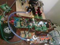
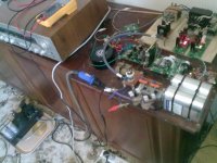
Attachments
Hi all,
if anyone was interested in the custom Laptech crystal
http://www.diyaudio.com/forums/grou...hronous-i2s-s-pdif-fifo-kit-group-buy-70.html
please add your name in the wish list at
http://www.diyaudio.com/forums/digital-line-level/203511-any-good-tda1541a-dac-kit-96.html
The minimum orderable quantity from Laptech is 5 pcs for each frequency.
When that quantity will be reached I ask Laptech for a quote.
Andrea
if anyone was interested in the custom Laptech crystal
The minimum orderable quantity from Laptech is 5 pcs for each frequency.
When that quantity will be reached I ask Laptech for a quote.
Andrea
Dear Andrea:
Which models of Laptech were you looking at? XOs or just straight crystals? (I'm not interested in OCXOs)
I have not been able to find any phase noise graphs or specs on their crystals. Do you have something to share that shows they are more special than something nice from say NDK?
Thanks,
AJC
You cannot find the specs on the Laptech website, since it's a custom crystal.
It's an AT-cut crystal (not suitable for OCXO) follow the specs for a 11.2896MHz:
cold welded
HC43/U package
10 ohm ESR or less
Q around 150K
strong polished
Hello Ian,
Hope you are well!
I am assisting a fellow Australian in connecting up the i2stoPCM to a TDA1541 ... I had a look at your PCB layout in post 242 and noticed the silkscreen in the manual for DCOUT/GND on TP9/TP1 appears to be back to front. He has the boards so I dont have one handy to poke at, could you confirm the polarity for the connection to the isolator board from these test points? I think TP9 should be +ve output rather than GND.
I also noticed that these connections are not mentioned in the manual, would be handy to have them mentioned if ever a new revision to the i2s to PCM converter manual is released.
Regards,
Chris
HI Ian
could You set by the code line
for 14bit stopped clock for TDA1540 dac?
maybe instead of 18bit pin conn?
Same like for the TDA1541A in COB format, but only 14bit bit-clock pulses from MSB
I think that is not complex operation, just exchanging the software variable from 16 to 14? Or I am wrong?
thanks
- Home
- Source & Line
- Digital Line Level
- Drive NOS AD1865/62,PCM1704/02/63,TDA1541 from FIFO: Universal I2S-PCM driver board