TDA1541 offset binary solution, please confirm
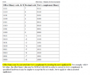
1. “Offset binary may be converted into two's complement by inverting the most significant bit.” So, to get an offset binary data format on both DL and DR which were two's complement format, I just need invert the MLB if the corresponding jumper is set for TDA1541. Is that OK?
2. To run NOS DAC’s at differential mode, we need a group of the reversed left and right data. For an I2S format (which is two’s complement), this usually can be done by just inverting the data line.
So, nDL=~DL; nDR=~DR;
The only problem is that will result in adding 1 LSB DC offset on the DAC output. Because the real reversed data should be equle to ~data +1.
Is there any problem on the 1 LSB DC offset? Or, it’s not an issue?
3. Method 2 will apply to data in offset binary format the same way as two’s complement to get the reversed data.
If all answers are yes, the offset binary mode would be no difficult to achieve.
Ian
Attachments
Last edited:
TDA1541 offset binary solution
Hi Ian,
thank you for your time and efforts used for such DIY gems.
In my humble opinion inverted I2S or offset binary stream for differential TDA1541 DAC is ok.
Because 1 LSB DC offset is permanent and really small (about 60nA),
such DC offset can be simply ignored, especially in cases if there are 2mA current injection circuits on the TDA1541 outputs.
1. “Offset binary may be converted into two's complement by inverting the most significant bit.” So, to get an offset binary data format on both DL and DR which were two's complement format, I just need invert the MLB if the corresponding jumper is set for TDA1541. Is that OK?
2. To run NOS DAC’s at differential mode, we need a group of the reversed left and right data. For an I2S format (which is two’s complement), this usually can be done by just inverting the data line.
So, nDL=~DL; nDR=~DR;
The only problem is that will result in adding 1 LSB DC offset on the DAC output. Because the real reversed data should be equle to ~data +1.
Is there any problem on the 1 LSB DC offset? Or, it’s not an issue?
3. Method 2 will apply to data in offset binary format the same way as two’s complement to get the reversed data.
If all answers are yes, the offset binary mode would be no difficult to achieve.
Ian
Hi Ian,
thank you for your time and efforts used for such DIY gems.
In my humble opinion inverted I2S or offset binary stream for differential TDA1541 DAC is ok.
Because 1 LSB DC offset is permanent and really small (about 60nA),
such DC offset can be simply ignored, especially in cases if there are 2mA current injection circuits on the TDA1541 outputs.
Hey all.
Quick question about using this with a PCM1704.
As PCM1704 kits are few and far between, are there any DACs out there that are easy enough to modify to incorporate this driver (as well as the reclock kit) ? There are a few "cheap" dacs on ebay, as well as the audio-gd dacs, all in the sub $1000 bracket.
Last edited:
What about a good I/V stage for the 1704? Now that Mr.Borbely is no longer providing kits what would be a good(read best ever) option? Asking because Peter who created the Phasure NOS1 DAC once said that you must die a thousand deaths to make it right and has stuck in my head paralyzing me to make a decision...
1. “Offset binary may be converted into two's complement by inverting the most significant bit.” So, to get an offset binary data format on both DL and DR which were two's complement format, I just need invert the MLB if the corresponding jumper is set for TDA1541. Is that OK?
2. To run NOS DAC’s at differential mode, we need a group of the reversed left and right data. For an I2S format (which is two’s complement), this usually can be done by just inverting the data line.
So, nDL=~DL; nDR=~DR;
The only problem is that will result in adding 1 LSB DC offset on the DAC output. Because the real reversed data should be equle to ~data +1.
Is there any problem on the 1 LSB DC offset? Or, it’s not an issue?.
Yes it is a problem, must run two's compliment at 32fs, see original 16 bit Phillips I2S standard. Makes a CD a 15 bit system which is already "hurting" for resolution. (See the other place for a good discussion about the issue.)
Last edited:
What about a good I/V stage for the 1704? Now that Mr.Borbely is no longer providing kits what would be a good(read best ever) option? Asking because Peter who created the Phasure NOS1 DAC once said that you must die a thousand deaths to make it right and has stuck in my head paralyzing me to make a decision...
Here you can still buy Erno's I'V stage, but its really just a discrete opamp.
LB-437IVL - A WebsiteBuilder Website.
There are many other solutions and opinions, Euvl on here has a good one called the Sen.
I like simply passive I/V + jfet or tube gain (w/filtering.).
Yes it is a problem, must run two's compliment at 32fs, see original 16 bit Phillips I2S standard. Makes a CD a 15 bit system which is already "hurting" for resolution. (See the other place for a good discussion about the issue.)
regal,
The I2S to PCM daughter board will precess and output data in true 16bit word format if you set the jumper for TDA1541.
The 1 LSB DC offest issue is only connected with data reversing for differential mode or dual mono mode. To reverse the data, it will invert all bits within a word.
I didn't see the reversing has anything to do with 32/16 bit word length issue.
Let me know what your are concerned about.
Regards,
Ian
Last edited:
regal,
The I2S to PCM daughter board will precess and output data in true 16bit word format if you set the jumper for TDA1541.
The 1 LSB DC offest issue is only connected with data reversing for differential mode or dual mono mode. To reverse the data, it will invert all bits within a word.
I didn't see the reversing has anything to do with 32/16 bit word length issue.
Let me know what your are concerned about.
Regards,
Ian
I see what you mean know. Couldn't you convert from i2s to two's compliment at 32 bit then truncate down to 16 bit, that way the LSB would be preserved ?
There are three advantages to 2's compliment with the tda1541a:
1. dual differential
2. dual mono
3. 8xfs (prior to fifo).
Any of three would be negated should we lose the LSB, so I guess I am in the all or nothing camp as far as two's compliment conversion for tda1541 goes (its a touchy subject for many.)
You wouldn't want your design to be less than the best if it is offering this mode I think. The TDA1541A's LSB is its claim to fame in a way, it was developed at a time when there were only 14 bit DAC's, and phillips did a huge amount of engineering to get that 16 bit resolution to match a RBCD standard. Best not offer it on this design if its only 15 bit resolution maybe rev 2 things will fall into place, just my opinion.
regal,
You didn't get my point on the calculation. With the dac working at dual mono differential mode, we didn't lose the LSB, we just got 1 DC offset added on the output.
If the data is A, take 16 bit for example , the range of A will be -32768 to +32767;
With the all bits inverting method I want to use, the differential output will be 2*A+1,
The range of A didn't have any change, but we get a doubled output of A plus 1. Did we lose any resolution?
The invert calculation will apply on all bit and doesn't matter it's 16bit or 32bit.
Regards,
Ian
Not complaining just know this issue has been gone over by a lot of enthusiasts.regal,
You didn't get my point on the calculation. With the dac working at dual mono differential mode, we didn't lose the LSB, we just got 1 DC offset added on the output.
If the data is A, take 16 bit for example , the range of A will be -32768 to +32767;
With the all bits inverting method I want to use, the differential output will be 2*A+1,
The range of A didn't have any change, but we get a doubled output of A plus 1. Did we lose any resolution?
The invert calculation will apply on all bit and doesn't matter it's 16bit or 32bit.
Regards,
Ian
I hear what you are saying but I would think the "digital" offset would cause a clipping at max output, no ? I guess we need to try and measure.
Not complaining just know this issue has been gone over by a lot of enthusiasts.
I hear what you are saying but I would think the "digital" offset would cause a clipping at max output, no ? I guess we need to try and measure.
Hi regal
at first, it looks you are right: inverting word of all 16x0 to all 16x1 ( or vice verso) should cause clipping.
But we are talking here about two differential data streams: one as it is, another inverted, both from same source.
I can not understand how can be any clipping in inverted stream if it is simply mirrored and here is no any clipping in source?
Do you have personal experience with clipping of inverted data stream?
Good to know thatI hear what you are saying
")
but I would think the "digital" offset would cause a clipping at max output, no ? I guess we need to try and measure.
We are talking about the +1 DC offset introducing to 2's complement format by inverting it for DAC in differential mode. To make it easier, I take 4 bit for example:
For a 4bit 2's complement format, the range will be -8(1000 min) to +7(0111 max).
If A=+7 (0111, max), the inverting result will be -8 (1000), so the differential output would be +7 - (-8) = +15, it's exactly 2*A+1;
OK, If A=-8 (1000, min), the inverting result will be +7 (0111), so the differential output would be -8 - (+7) = -15, it's also 2*A+1;
And more, If A=0 (0000), the inverting result will be -1 (1111), so the differential output would be 0 - (-1) = 1, still 2*A+1;
It's just a 2'complement converting method, I didn't see there is any problem except the +1 issue.
But agree with you, I have to have some test, just to confirm. But I no longer keep my old TDA1541 DAC now
.Regards,
Ian
Good to know that
We are talking about the +1 DC offset introducing to 2's complement format by inverting it for DAC in differential mode. To make it easier, I take 4 bit for example:
For a 4bit 2's complement format, the range will be -8(1000 min) to +7(0111 max).
If A=+7 (0111, max), the inverting result will be -8 (1000), so the differential output would be +7 - (-8) = +15, it's exactly 2*A+1;
OK, If A=-8 (1000, min), the inverting result will be +7 (0111), so the differential output would be -8 - (+7) = -15, it's also 2*A+1;
And more, If A=0 (0000), the inverting result will be -1 (1111), so the differential output would be 0 - (-1) = 1, still 2*A+1;
It's just a 2'complement converting method, I didn't see there is any problem except the +1 issue.
But agree with you, I have to have some test, just to confirm. But I no longer keep my old TDA1541 DAC now
Regards,
Ian
I've got a blank red barron PCB and a TDA1541 I could send you when I send in my two fifo's for upgraded firmwares, just can't get away from work long enough to build the powersupplies and populate.
Thankyou for all the work on the fifo and now daughter board, its shaping up to be a really ground breaking design.
Hi, I'm also very interested in this board!
TOTAL = 55
TV Man x 2
merlin el mago
rtd
jameshillj
erin
Nikola Krivorov x 3
Rupor54
vitalica
analog_sa
andrea_mori x 5
dsavitsk
tagheuer
hirez69 x 2
ccliu
BDL
cddumat
regal
zoran
Jogi
Zen(zenelectro) x 2
Buzzforb
SPWON
crobbins5421 X 2
marcus1 X 2
casshan x 2
Dweeb99 X 2
jackw X 2
kazap X 2
danzup x 3
Giordano x2
Tony_T
Tubo x1
clivem x2
noizas x2
JoeyDD x2
I've got a blank red barron PCB and a TDA1541 I could send you when I send in my two fifo's for upgraded firmwares, just can't get away from work long enough to build the powersupplies and populate.
Thankyou for all the work on the fifo and now daughter board, its shaping up to be a really ground breaking design.
Thanks regal for offering the PCB. But I'm afraid I need a pair of differential mode 1541 DAC with offset binary jumper. Just let me figure out if I could source them.
You can send the fifo back to me at any time for upgrade. Still keep my address tag?
Have a nice weekend.
Ian
Offset Binary format option for TDA1541 achieved
PcmTransmitter.v
"......
//2013-01-19 Add offset binary format jumper for TAD1541 OB mode
//2013-01-20 Optional offset binary output achieved
......
module PcmTransmitter(
reset, //system reset
mclk, //system clk
obflagn, //offset binary format flag
......
);
…...
endmodule
"
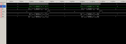
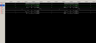
Please see the actual measurement screen shot from my logic analyzer for details.
Tested at 384Khz Fs with MCLK=256Fs.
Ian
PcmTransmitter.v
"......
//2013-01-19 Add offset binary format jumper for TAD1541 OB mode
//2013-01-20 Optional offset binary output achieved
......
module PcmTransmitter(
reset, //system reset
mclk, //system clk
obflagn, //offset binary format flag
......
);
…...
endmodule
"
Please see the actual measurement screen shot from my logic analyzer for details.
Tested at 384Khz Fs with MCLK=256Fs.
Ian
Attachments
- Home
- Source & Line
- Digital Line Level
- Drive NOS AD1865/62,PCM1704/02/63,TDA1541 from FIFO: Universal I2S-PCM driver board